AI




Grounding and bonding takeoff is easy to under-scope in a commercial electrical bid. A ground rod symbol may be visible on the site plan, while conductor routes, structural steel connections, bonding hardware, and testing obligations are scattered across electrical details and Division 26 specifications. A missed connection can mean more than a material adjustment: grounding deficiencies may delay inspection, energization, or turnover.
Table of Сontents
For an estimator preparing an electrical grounding takeoff, the question is not simply whether the design shows a ground. It is what to count, what to measure, what another trade supplies, and how to price installation. This guide covers service electrodes, grounding electrode conductors, equipment grounding conductors, bonding jumpers, and specialty grids, with NEC Article 250 references that matter when assembling a defensible commercial or industrial bid.
This is a takeoff and pricing workflow, not a replacement for the approved engineering design, project specifications, or the NEC edition adopted by the authority having jurisdiction (AHJ).
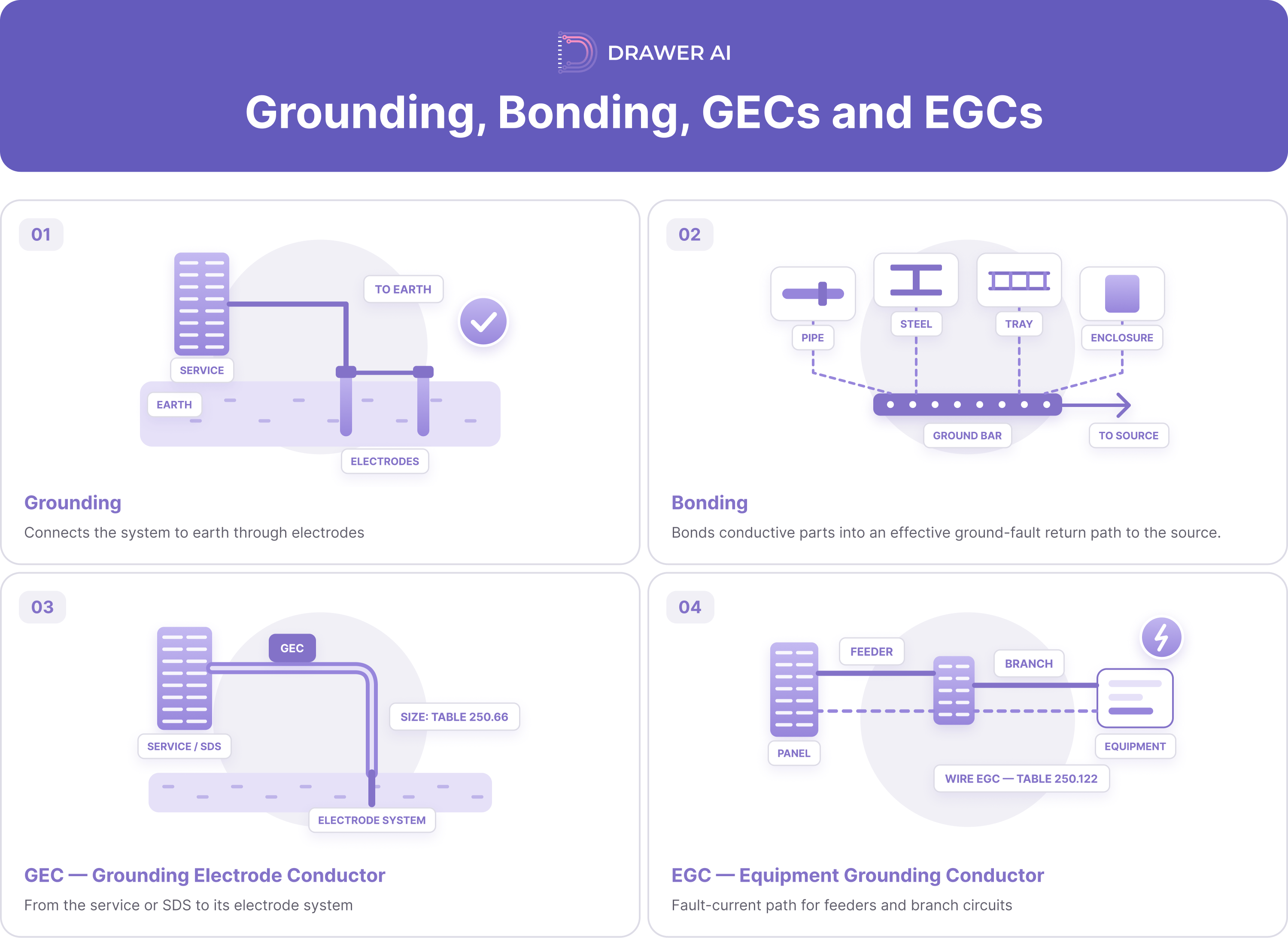
Grounding connects a system or equipment to earth through a grounding electrode system; bonding establishes electrical continuity among conductive parts to help create an effective ground-fault current path. A grounding electrode conductor (GEC) connects the applicable system to its electrode system. An equipment grounding conductor (EGC), whether a wire or a permitted wiring method, serves the equipment fault-current path. Those functions create different takeoff quantities. A service GEC run does not replace the EGC quantities associated with feeders and branch circuits. NEC Article 250 addresses these functions for the conventional commercial power installations covered here. Separate each path, connection, and installation assembly before assigning conductor sizes or labor units.
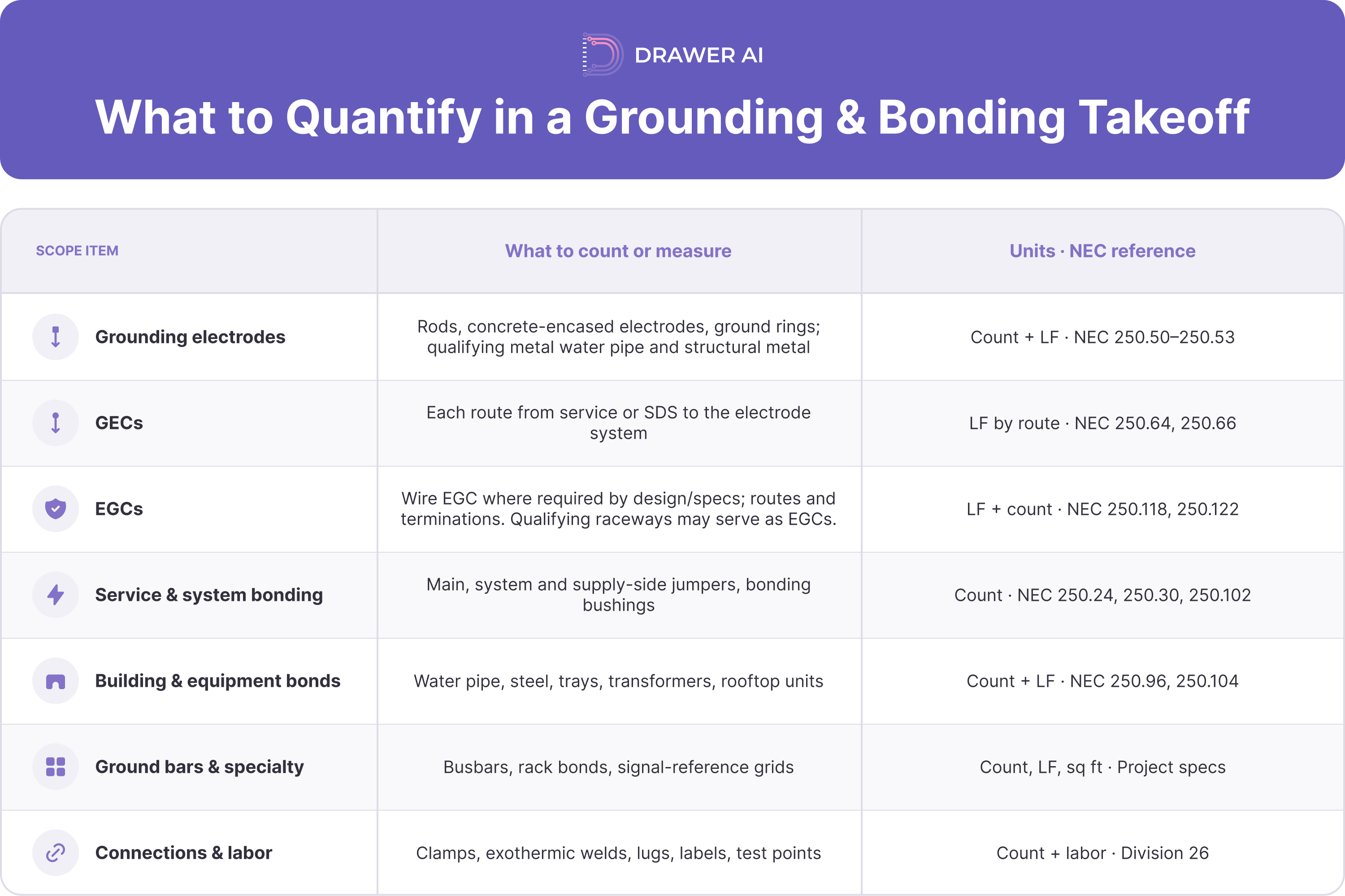
To determine what to include in a grounding takeoff, read plans, one-lines, site details, equipment schedules, and Division 26. Count each assembly once; measure conductor routes, not a blanket allowance. Build this scope register:
Keep separate takeoff codes for electrodes, GECs, EGCs, bonds, specialty systems, and testing. If a detail is repeated on a one-line and plan, reconcile the drawings to one installed assembly rather than counting it twice.
Copper footage and connection labor can outweigh the visible device count. A ground rod may be easy to mark, but its associated conductor, excavation, clamp, access, and test obligation are not captured by the symbol alone. A building-wide ground ring, long feeder EGCs, high-level steel bonds, or a specified signal-reference grid can drive materials and labor. For every item, distinguish conductor length from raceway length, and apply route or waste allowances only where justified by installation conditions.
Sizing mistakes also change costs. NEC Table 250.66 is the general GEC sizing reference based on the relevant service or system conductors, with electrode-specific provisions. Table 250.122 addresses wire EGC sizing based on the upstream overcurrent device and applicable adjustments. The tables are not interchangeable; verify whether circuit conductor upsizing, parallel raceways, or project-specific requirements change the material count. Use the approved design and adopted code rather than reproducing a generic size chart in the estimate.
Installation details carry inspection exposure. An inaccessible electrode connection, unsuitable fitting, omitted steel bond, or missing jumper at a separately derived transformer can require rework before energization. Price specified inspections and testing, including access to concealed work and documentation. Record whether utility, owner, concrete, structural, mechanical, or low-voltage contractors supply each item so exclusions and overlaps are visible.
NEC grounding and bonding requirements set the code baseline for the applicable installation; Division 26 can require additional ground bars, conductors, installation methods, or testing. The AHJ and locally adopted edition govern code compliance.
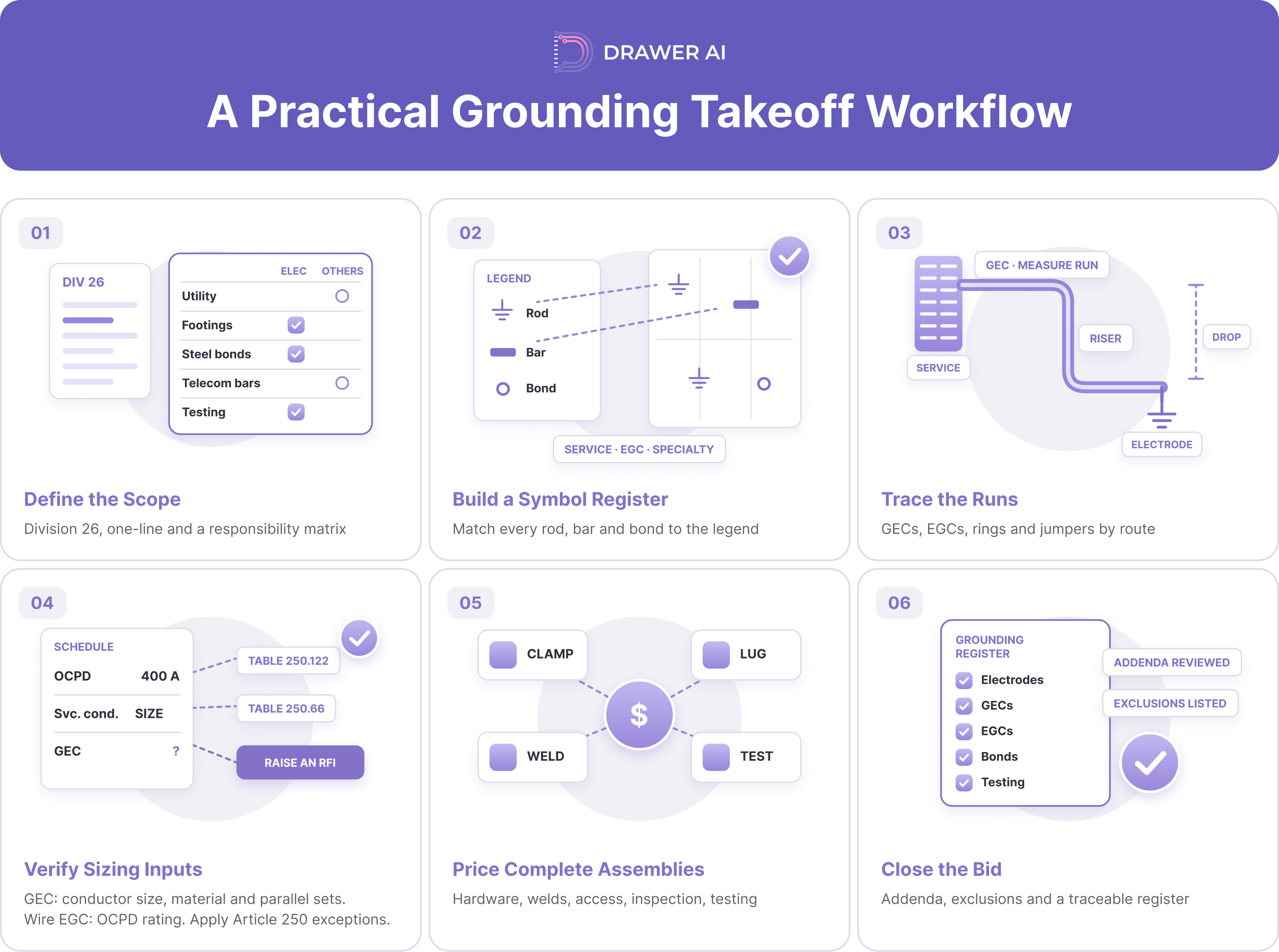
Step 1 — Define scope. Read Division 26, the one-line, grounding details, site plan, and coordination notes. Create a responsibility matrix covering utility work, footing electrodes, steel bonds, telecommunications bars, and testing.
Step 2 — Build a symbol register. Match each ground rod, bar, bonding point, and electrode notation to the legend. Separate service grounding, feeder and branch-circuit EGCs, and specialty grounding systems.
Step 3 — Trace the runs. Measure GECs, wire EGCs, ground rings, and bonding jumpers by conductor type and physical route. Include risers, drops, offsets, and documented routing assumptions, but keep conductor, conduit, and excavation quantities distinct.
Step 4 — Verify sizing inputs. Check approved schedules, equipment ratings, upstream overcurrent devices, and the applicable Article 250 provisions. If a conductor size or bonding detail is missing, raise it for qualified design review instead of guessing.
Step 5 — Price complete assemblies. Add connection hardware, supports, corrosion protection, access equipment, excavation, welding, terminations, inspection, and testing labor. Reconcile repeated drawing details before extending unit costs.
Step 6 — Close the bid. Cross-check against the one-line and equipment schedule, review addenda and the adopted NEC edition, and document exclusions and trade responsibilities. Retain a traceable electrical grounding takeoff register for bid clarifications and change orders.
For the wider bid sequence, see our commercial and industrial electrical estimating guide.
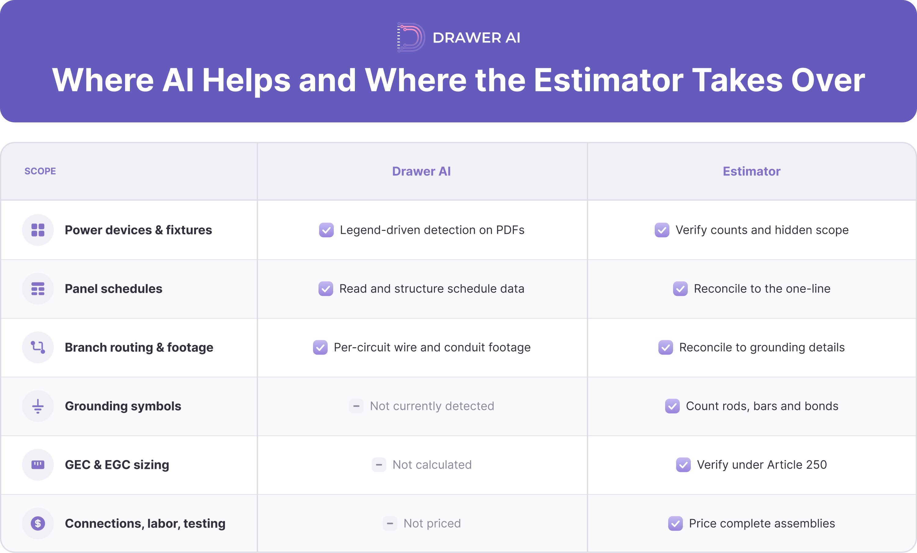
At Drawer AI, we use legend-driven detection on PDF electrical drawings to count power devices, lighting fixtures, and panel schedules, and we generate branch-circuit routing with per-circuit wire and conduit footage. That routed output gives estimators circuit-level conductor and footage data to reconcile against the one-line, grounding details, and equipment schedules. This gives estimators a starting point to reconcile against the one-line, grounding details, and equipment schedules.
We do not calculate Article 250 grounding requirements or independently size GECs or EGCs. The estimator identifies hidden scope, verifies conductor sizes and bonds with the approved design, and prices connections, specialty installations, labor, and testing. A symbol count is not a complete grounding estimate.
For circuit conductor and raceway methods, see our conductor and raceway sizing guide. For conduit-fill and load-calculation references, see our NEC reference guide (its load-calculation citations use 2023 numbering). Verify GEC and EGC sizing separately under Article 250, including Table 250.122 for wire EGCs.
Ready to speed up the device-counting and circuit-quantity portion of your next commercial bid? Explore our electrical takeoff workflow or book a demo of Drawer AI.

14425 Falcon Head Blvd
Building E, Suite 100,
Austin, TX 78738
Created by Estimators, Powered by AI and Innovation
Copyright © 2026 Drawer AI. All rights reserved.