AI




Every commercial electrical estimator eventually faces the same challenge: a multi-story project arrives with hundreds of drawing sheets and a tight bid deadline. While inexperienced estimators begin counting fixtures and receptacles, seasoned professionals turn first to a single, often overlooked drawing the electrical riser diagram. Understanding this document early transforms a chaotic takeoff into a structured, systematic process.
This guide explains what an electrical riser diagram is, how its components fit together, and how to extract maximum value from it during a commercial electrical estimate.
Table of Сontents
So where does your scope begin and end, and what do you actually need to carry? This article breaks down what low voltage means in construction, how scope is commonly split across trades, and where estimators most often get exposed if they rely on assumptions instead of the documents.
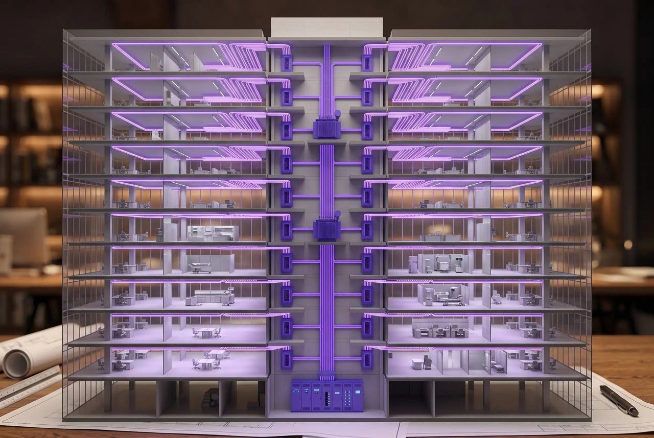
An electrical riser diagram also called a power riser diagram is a simplified single-line drawing that illustrates how electrical power travels vertically through a commercial building. Unlike a floor plan, which depicts the physical location of devices within a level, the riser diagram presents the distribution system in logical form: where power enters the building, how it moves upward, and where it terminates at distribution equipment on each floor.
Most electrical drawing sets contain the riser diagram within the "E" sheets, alongside one-line diagrams, panel schedules, and distribution details. On larger projects, multiple riser diagrams may exist one each for normal power, emergency power, life safety, and generator distribution.
For the estimator, the riser diagram functions as a project roadmap. Within minutes of reviewing it, a skilled estimator can identify the major distribution equipment, primary feeder runs, transformer locations, and overall system voltage before opening a single floor plan.
Understanding how the riser diagram relates to other common drawings prevents confusion and reduces errors during take-off.
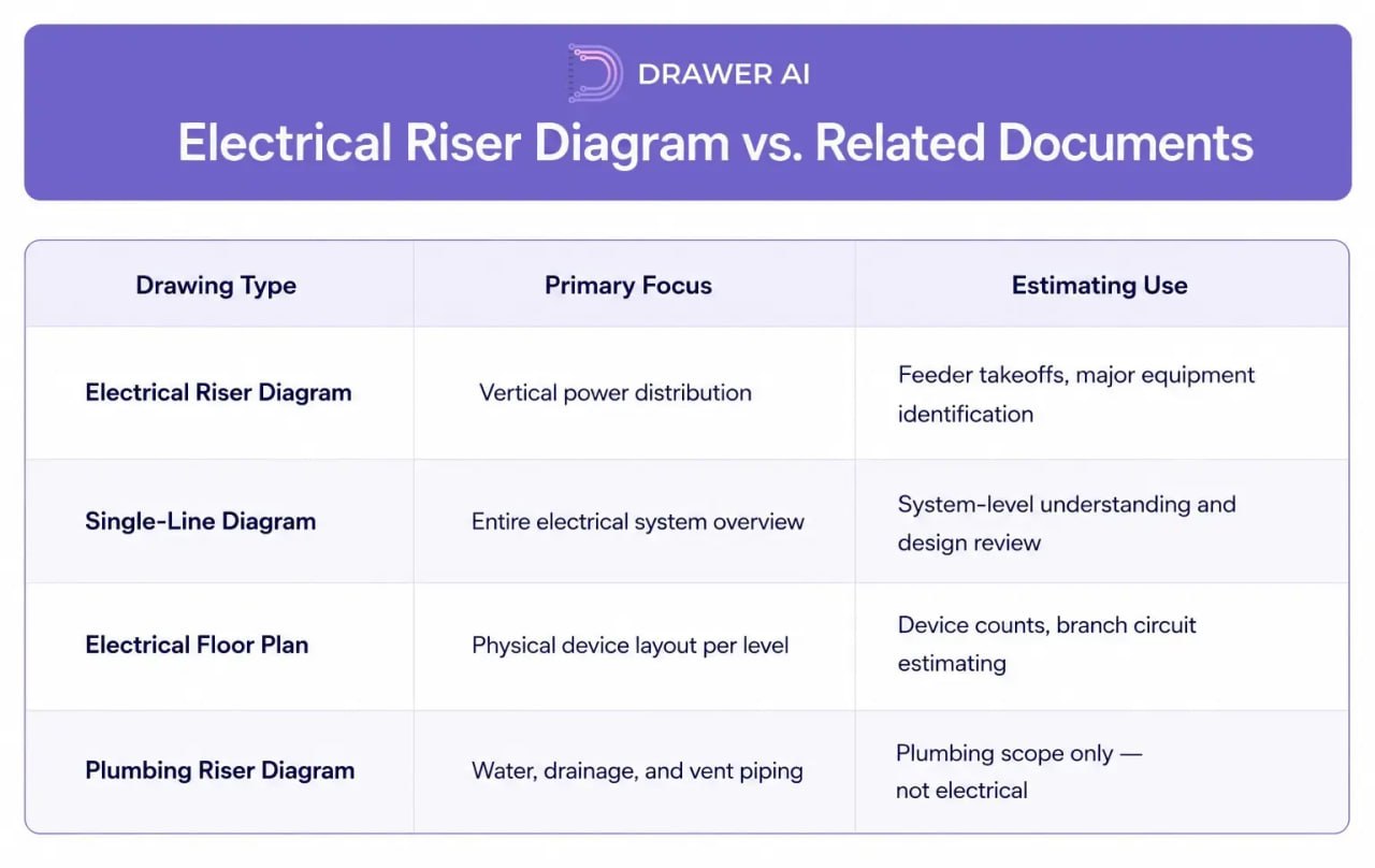
The electrical riser and the single-line diagram share a similar appearance, but the riser places greater emphasis on the vertical movement of power from one floor to the next. Neither should be confused with a plumbing riser diagram, which represents an entirely different building system despite sharing the term "riser."
Most commercial electrical riser diagrams follow a consistent, bottom-to-top layout. Power enters at the bottom of the drawing and is distributed upward through progressively smaller equipment until it reaches branch circuit panelboards on each floor. Learning this anatomy makes reading any new riser diagram significantly faster.
The service entrance is the starting point of every riser diagram. This is where power arrives from the utility company and enters the building's electrical system. Key information shown here includes service voltage (e.g., 480Y/277V), available ampacity, metering equipment, main disconnects, and the utility transformer if located on-site.
For estimators, the service ampacity immediately signals the scale of the project. A 400A service indicates a modest commercial facility; a 2,500A or 4,000A service suggests a hospital, data center, or high-rise building with substantially more distribution equipment and feeder materials.
Immediately downstream of the service entrance sits the Main Switchboard (MSB) or Main Switchgear — the building's primary distribution hub. This equipment receives power directly from the utility, protects the system through overcurrent devices, and distributes power to all downstream equipment.
The MSB is typically one of the most expensive single items in the electrical estimate. Its rating including bus ampacity, main breaker size, short-circuit withstand rating, and voltage defines the upstream boundary of the entire distribution system. Identifying it early allows the estimator to size the project and allocate budget before beginning detailed takeoffs.
The Main Distribution Panel (MDP) acts as the central hub from which feeders branch out to every major system in the building distribution panels, transformers, mechanical equipment, elevators, fire pumps, busway risers, and emergency systems.
Feeders are the most material-intensive items on the riser diagram. Each feeder callout typically specifies the number of conductors, conductor size (e.g., 500 kcmil CU), ground conductor, conduit size and type (e.g., 4" EMT), and the destination equipment. Missing a single feeder run can create a significant gap in the material take-off.
%20and%20Feeders.jpg?width=1280&height=782&name=Main%20Distribution%20Panel%20(MDP)%20and%20Feeders.jpg)
Experienced estimators trace each feeder individually from source to destination, recording the above data in a worksheet before touching the floor plans. By the time the riser review is complete, the foundation of the feeder takeoff is already built.
In multi-story commercial buildings, particularly hospitals, hotels, office towers, and universities, a vertical busway often replaces individual feeder conduits running to every floor. A busway is a factory-assembled distribution system that carries high current loads vertically, with floor-level tap boxes providing connection points for distribution equipment on each level.
When a busway is present, the estimator must account for the total vertical busway length, the number of floor tap units, expansion fittings, supports, fire-stopping assemblies, and termination hardware. Recognizing a busway early prevents the common error of double-counting both conduit feeders and busway materials for the same circuit.
Many commercial buildings operate at two voltage levels. A typical arrangement uses 480Y/277V for lighting and large mechanical loads, with step-down transformers converting power to 208Y/120V for receptacles, office equipment, and smaller branch circuits.
Each transformer symbol on the riser diagram includes the kVA rating, primary voltage, secondary voltage, connection type, and equipment tag (e.g., T-3, 112.5 kVA, 480V → 208Y/120V). Every transformer creates additional feeder runs on both the primary and secondary sides, meaning additional conductors, conduit, terminations, and labor that must be captured in the estimate.
Distribution panelboards appear on each floor, identified by unique tags such as LP-1, PP-2, DP-A, or MDP-3. These tags correspond to panel schedules elsewhere in the drawing set, which provide circuit counts, breaker ratings, and connected loads.
Floor reference lines divide the riser diagram horizontally, representing building levels from basement to penthouse. This vertical layout allows the estimator to determine how many floors are served by each piece of distribution equipment, where panels are located, and which feeders travel the greatest vertical distances — useful information for preliminary conduit length calculations before floor plans are reviewed.
On any project with a standby generator, the Automatic Transfer Switch (ATS) is the component that ties the normal and emergency power systems together. When utility power fails, the ATS senses the loss and transfers the emergency loads from the normal source to the generator, then transfers them back once utility power is restored. On the riser diagram it appears between the main distribution equipment, the generator, and the emergency distribution panel it serves.
For the estimator, the ATS is major standalone equipment and one of the higher-cost items on the emergency riser. It is easy to overlook because it sits quietly between the generator and the emergency panel, but skipping it removes both a significant piece of equipment and a full set of feeders from the takeoff. Each ATS is defined by its ampere rating, voltage, number of poles, and transition type (open, closed, or delayed), all of which affect both cost and the conductor and conduit sizing on either side of it.
Every ATS creates additional feeder connections that must be captured separately: the normal-source feeder arriving from the main distribution equipment, the emergency-source feeder arriving from the generator, and the load-side feeder continuing to the emergency distribution panel. Trace each of these the same way as any other feeder, recording conductor count and size, ground conductor, and conduit size and type. Recognizing the ATS and its feeders during the riser review prevents a common and expensive omission on the emergency side of the estimate.
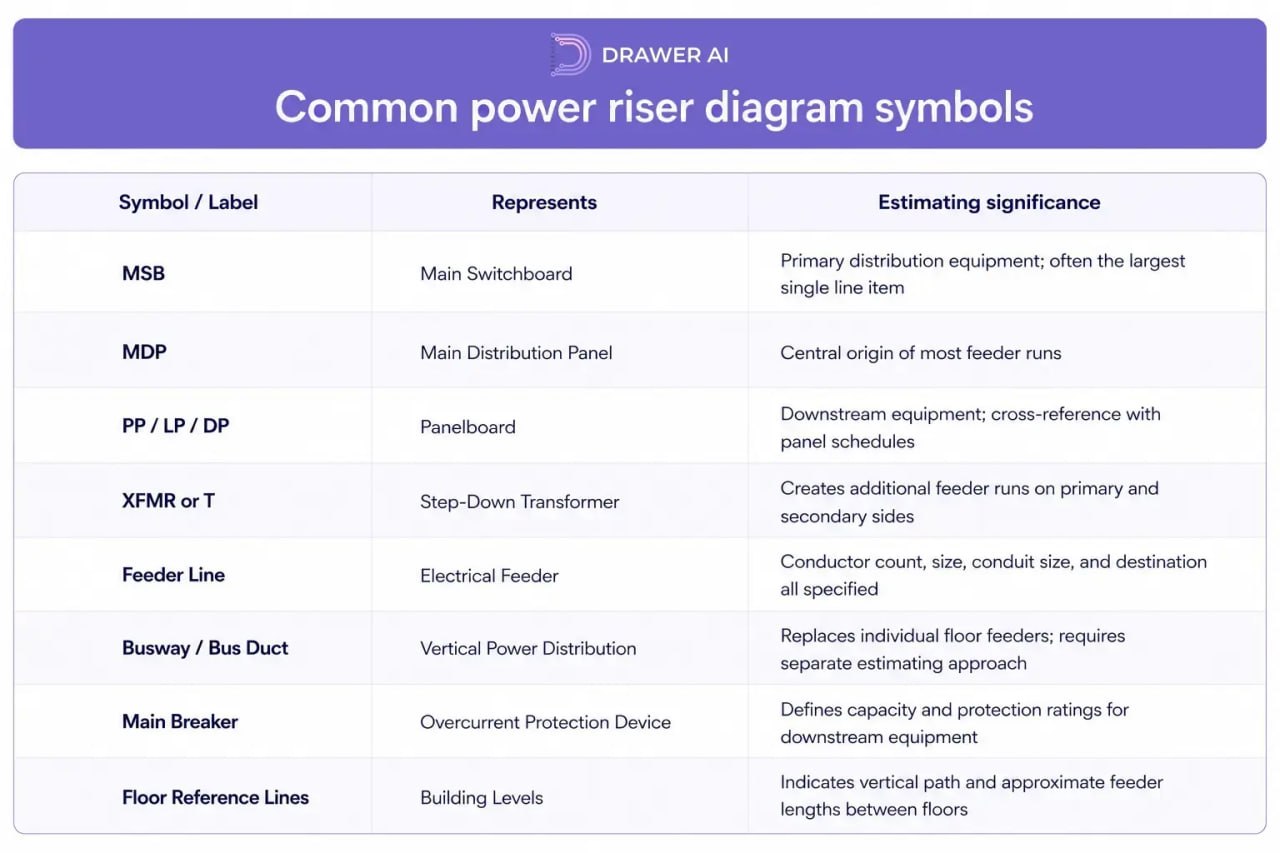
Electrical riser diagrams use standardized symbols that vary slightly between engineering firms but remain consistent in meaning. The table below covers the symbols most frequently encountered on commercial projects.
Experienced estimators follow a consistent sequence when reviewing the electrical riser diagram. This workflow reduces omissions, prevents duplicate quantities, and ensures that the most expensive distribution equipment is identified before the detailed floor-plan takeoff begins.
Begin at the bottom of the drawing. Record the service voltage, ampacity, metering configuration, and main switchboard rating. This single step reveals the overall scale of the project and prevents surprises when large distribution equipment appears later in the estimate.
Locate the MSB, MDP, and any switchgear immediately downstream of the service. Count the outgoing feeders from each piece of major distribution equipment. Each departing feeder represents conductors, conduit, supports, pull boxes, and terminations that must be included in the estimate.
Follow each feeder individually from origin to endpoint. Do not skip between drawing areas. Record the conductor quantity and size, ground conductor, conduit size and type, and destination equipment. Completing this step before opening floor plans provides the framework for the entire feeder take-off.
Each transformer on the riser creates two feeder sections: the primary feeder supplying the transformer and the secondary feeder leaving it. Both sides require separate material quantities. Note the kVA rating, voltage levels, and equipment tag for later cross-referencing with the panel schedules.
List every panelboard shown on the riser, including its tag, voltage, main breaker size, and source feeder. Compare this list against the panel schedules to confirm that no panel has been omitted from the drawing set. A missing panel schedule should trigger a clarification request before the bid is finalized.
If a vertical busway is present, determine the total run length, the number of floor tap units, and the termination details at both ends. Busway installations require a different estimating methodology than conventional conduit feeders, and recognizing this distinction early prevents quantity errors.
Before moving to the floor plans, confirm that each of the following has been identified and documented:
• Utility service entrance and metering
• Main switchboard or switchgear
• Main distribution panels
• All transformers (primary and secondary feeders)
• All panelboards and their source feeders
• Busway system (if present)
• Emergency and standby distribution
• Voltage transitions throughout the system
• Grounding and bonding equipment
The electrical riser diagram is also where many estimation errors originate. Being aware of these pitfalls significantly reduces the risk of costly omissions or over-counts.
A feeder shown on the riser may also appear on a floor plan or distribution detail. Always verify whether a quantity has already been counted in a prior takeoff step before adding it again.
The primary feeder supplying a transformer is usually easy to spot. The secondary feeder leaving the transformer and continuing to downstream panels is frequently overlooked. Both sides must be included in the takeoff with their full material quantities.
Floor plans rarely show the complete vertical routing of conduit between levels. The riser diagram provides the reference for estimating vertical conduit runs before field measurements are possible. Ignoring this step leads to systematic undercounting on multi-story projects.
The riser diagram and panel schedules must be consistent with each other. If a panel appears on the riser but its schedule is missing from the drawing set, the discrepancy should be flagged and resolved before the estimate is submitted.
The following scenario demonstrates how a riser review translates into preliminary take-off quantities on a realistic commercial project.
A six-story, 120,000-square-foot medical office building has an electrical riser diagram showing a 2,000A, 480Y/277V utility service feeding a main switchboard at ground level. A vertical busway serves a main distribution panel (MDP) on each of the six floors. A 112.5 kVA step-down transformer on Level 3 provides 208Y/120V power for receptacles and medical equipment. Lighting panels and power panels are present on every floor, and a standby generator supplies an emergency distribution panel.
Based solely on the riser diagram before reviewing a single floor plan the preliminary take-off might capture:
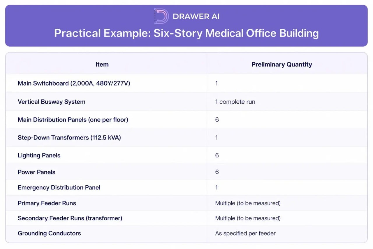
This early overview organizes the remainder of the estimating process. Rather than discovering equipment piece by piece across hundreds of floor plan sheets, the estimator approaches the detailed takeoff with a complete picture of the building's electrical backbone.
Reading the electrical riser is one job. Transcribing it is another. On every multi-story bid, the estimator copies each feeder, conductor and conduit run, and per-floor panel off the power riser into a spreadsheet, then does it again on the next revision. That transcription is slow, and it's where vertical-take-off errors creep in.
This is the part AI take-off tools are built to remove. Software that reads the plan set directly from the PDF can detect panels and equipment with their ratings, route branches, and stitch multi-page sets together automatically, turning the drawing into structured take-off data instead of a manual copy job. Drawer AI does this today for device and equipment take-off and branch routing, with feeder and plan-equipment detection on its roadmap, so the vertical take-off becomes data you check rather than type.
One honest boundary: Drawer AI is take-off-only. It produces quantities — feeders, panels, devices, conduit — that feed your estimating software; it does not apply labour units or price the job.
See how Drawer AI pulls feeders and equipment from your riser diagrams and plan set into structured takeoff data — book a demo.
The electrical riser diagram is among the most information-dense drawings in a commercial electrical plan set. A structured review starting at the service entrance, tracing every feeder, accounting for all transformers and busway systems, and cataloguing every distribution panel provides the foundation for an accurate, organized electrical estimate.
Estimators who master the riser review process reduce omissions, improve bid consistency across project revisions, and spend less time recovering from errors discovered late in the takeoff. Combined with thorough cross-referencing against panel schedules and one-line diagrams, the riser diagram transforms from an intimidating single-line drawing into the most powerful planning tool in the estimator's workflow.
As drawing sets grow larger and project timelines tighten, the ability to extract maximum intelligence from the riser diagram quickly before diving into floor plans remains one of the most valuable skills in commercial electrical estimating.

14425 Falcon Head Blvd
Building E, Suite 100,
Austin, TX 78738
Created by Estimators, Powered by AI and Innovation
Copyright © 2026 Drawer AI. All rights reserved.