
AI



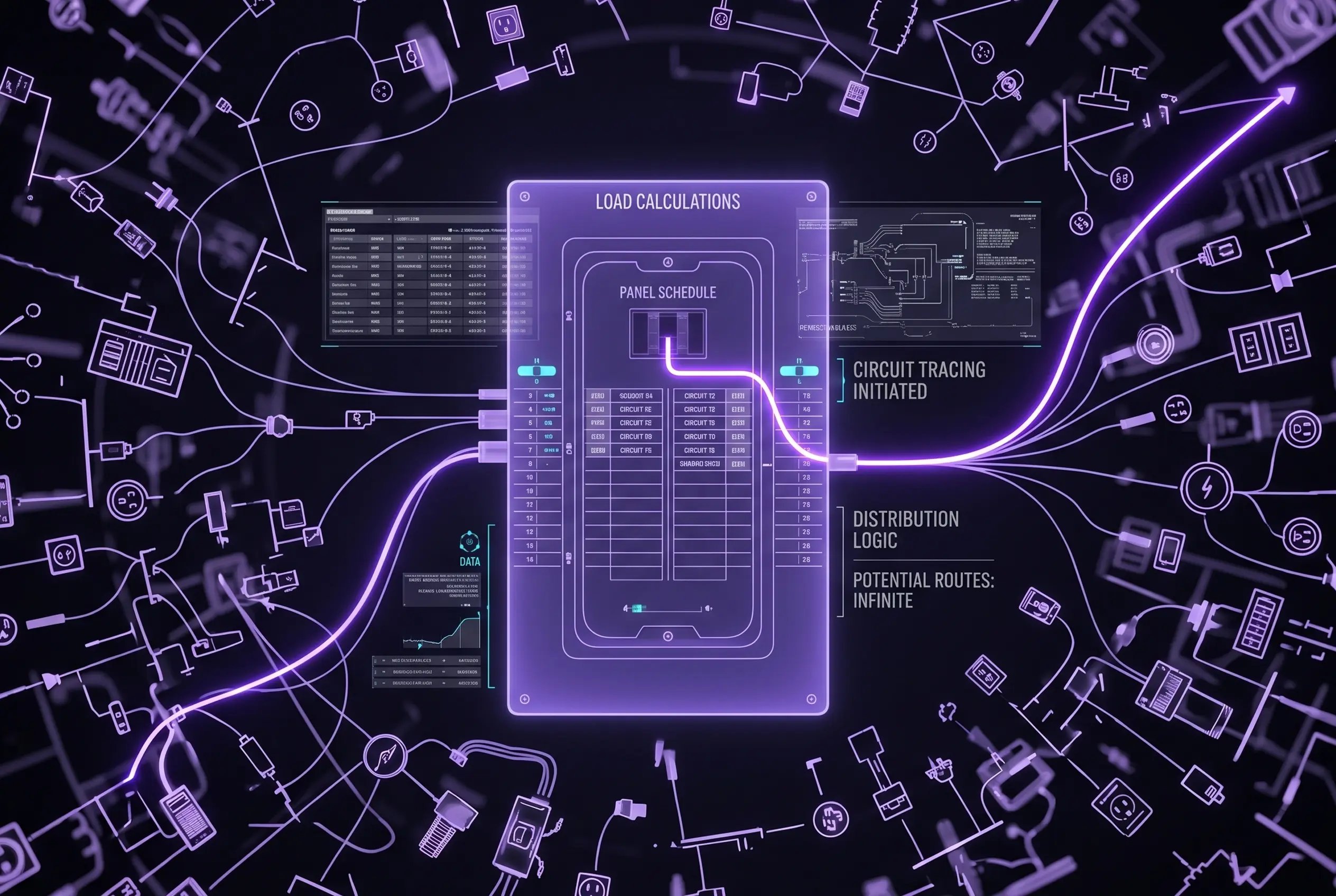

Picture an estimator working through a large commercial bid with multiple panels and a 200-circuit panel schedule in front of them. The plans show receptacles, equipment, and branch circuits everywhere, but the real challenge is tracing each device back to the right circuit and understanding how the distribution is organized. That is where the panel schedule becomes essential. In simple terms, a panel schedule is the document that identifies a panelboard’s circuits, loads, breakers, and connected equipment, giving estimators a fast way to verify scope and build accurate takeoffs.
This article is a practical reading guide for estimators who need to interpret electrical and 3-phase panel schedules in real project documents, not an exam-prep lesson. It focuses on how to read the schedule efficiently, connect it to the drawings, and use it to support clearer, more accurate takeoff.
Table of Сontents
A panel schedule is the tabulated document that lists the circuits in a panelboard and summarizes the key information estimators and electricians need to read quickly. Depending on the project and format, it may show circuit numbers, breaker sizes, phase positions, conductor information, connected loads, descriptions of the equipment served, and sometimes locations or remarks. In practice, it acts as the roadmap for how power is distributed through that panel, making it much easier to connect the design drawings to the actual electrical scope.
It is important to separate the panel schedule from the panelboard itself. The panelboard is the physical piece of electrical distribution equipment described in NEC Article 408. The panel schedule, by contrast, is the document or drawing-based reference that describes what is inside that equipment and how its circuits are assigned. For estimating, this distinction matters because you are often using the schedule to understand capacity, circuiting, and scope long before you ever see the installed hardware.
You will also hear several versions of the term used interchangeably. In code language, panelboard schedule is the more precise term, but in everyday construction and estimating conversations, panel schedule, panel board schedule, and electrical panel schedule are all commonly used to mean essentially the same thing. Knowing these variations helps when reviewing drawings, specifications, submittals, and search terms across different projects and teams.
There is also a code reason these schedules matter. NEC 408.4 requires circuits and circuit modifications to be legibly identified so the circuit directory clearly reflects their purpose or use. For estimators, that requirement reinforces the value of a well-prepared schedule: it is not just a drafting convenience, but a practical tool for interpreting the design accurately and checking whether the documentation is clear enough to support pricing and installation.
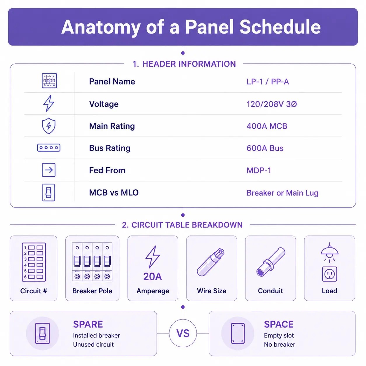
A panel schedule is easiest to read when you move from the top down. Start with the header information, which tells you what panel you are looking at and how it is fed. Then read across the circuit table, where each row and column explains how individual circuits are protected, wired, and assigned. For estimators, this top-to-bottom approach makes it easier to connect panel data to the drawings and spot scope gaps before pricing.
The header section gives you the panel’s identity and its basic electrical characteristics. These details help you confirm whether you are looking at the correct schedule and understand the panel’s role in the distribution system.
The circuit table is where the schedule becomes most useful for takeoff and scope review. Each column describes a different part of the branch circuit, from overcurrent protection to wiring method to the load being served.
A common point of confusion is the difference between spare and space. A spare is a breaker that is installed but not connected to a load, while a space is an unused slot with no breaker installed. This distinction matters when you are assessing future capacity, reviewing completeness, or determining whether added circuits will require new equipment. A clear panel schedule should label both clearly so available capacity is easy to identify.
Reading a 3-phase panel schedule starts with understanding the repeating phase pattern built into the panel bus. In a standard two-column layout, odd-numbered circuits appear on the left and even-numbered circuits on the right. As you move down the schedule, the phases repeat in sequence across the bus, typically A, B, and C. That pattern helps you identify which circuits share a phase, which ones form multi-pole breakers, and how branch circuits are distributed through the panel. For estimators, this is essential because it affects how you interpret feeder relationships, equipment connections, and available circuit capacity in commercial work.
Once you understand the layout, the next step is to read how the loads are arranged. In 3-phase systems, some circuits are line-to-neutral loads, such as 120V or 277V branch circuits, while others are line-to-line or fully 3-phase loads, such as larger equipment and motor connections. The schedule may also show whether the system includes a neutral and how grounding is handled, which helps you distinguish between 4-wire wye applications and configurations where a neutral may not serve every load. Good schedules make phase balancing easier to evaluate by showing how connected loads are spread across A, B, and C legs. That balance matters for service performance, neutral loading, and realistic estimating.
Note whether the panel is main breaker (MCB) or main lug only (MLO). That affects how the panel is protected and changes how you interpret the relationship between the main device rating and the bus rating.
Color references can add another layer of clarity when you read a 3-phase panel schedule. In many U.S. commercial 120/208V systems, the common phase convention is black, red, and blue for phases A, B, and C. In many 277/480V systems, the common convention is brown, orange, and yellow. Neutral and grounding conductors follow separate identification rules, while phase colors for ungrounded conductors are often based on established industry practice rather than a single mandatory national color set. Some firms also use internal color-coding on schedules to flag spare spaces, dedicated circuits, emergency loads, or specific load types. Those markings are helpful, but they are office conventions rather than universal standards, so they should always be read in context with the schedule legend and project notes.
For estimators, a panel schedule is not just a reference table. It is a working tool that helps translate the design into measurable scope. When you read the schedule alongside the floor plan and the electrical symbols, you can trace how individual devices connect to circuits, how those circuits route back to a panel, and how that panel is supplied. That chain is what turns a set of drawings into a practical takeoff.
A useful way to think about the process is to move from the smallest visible item on the plan back to the source:
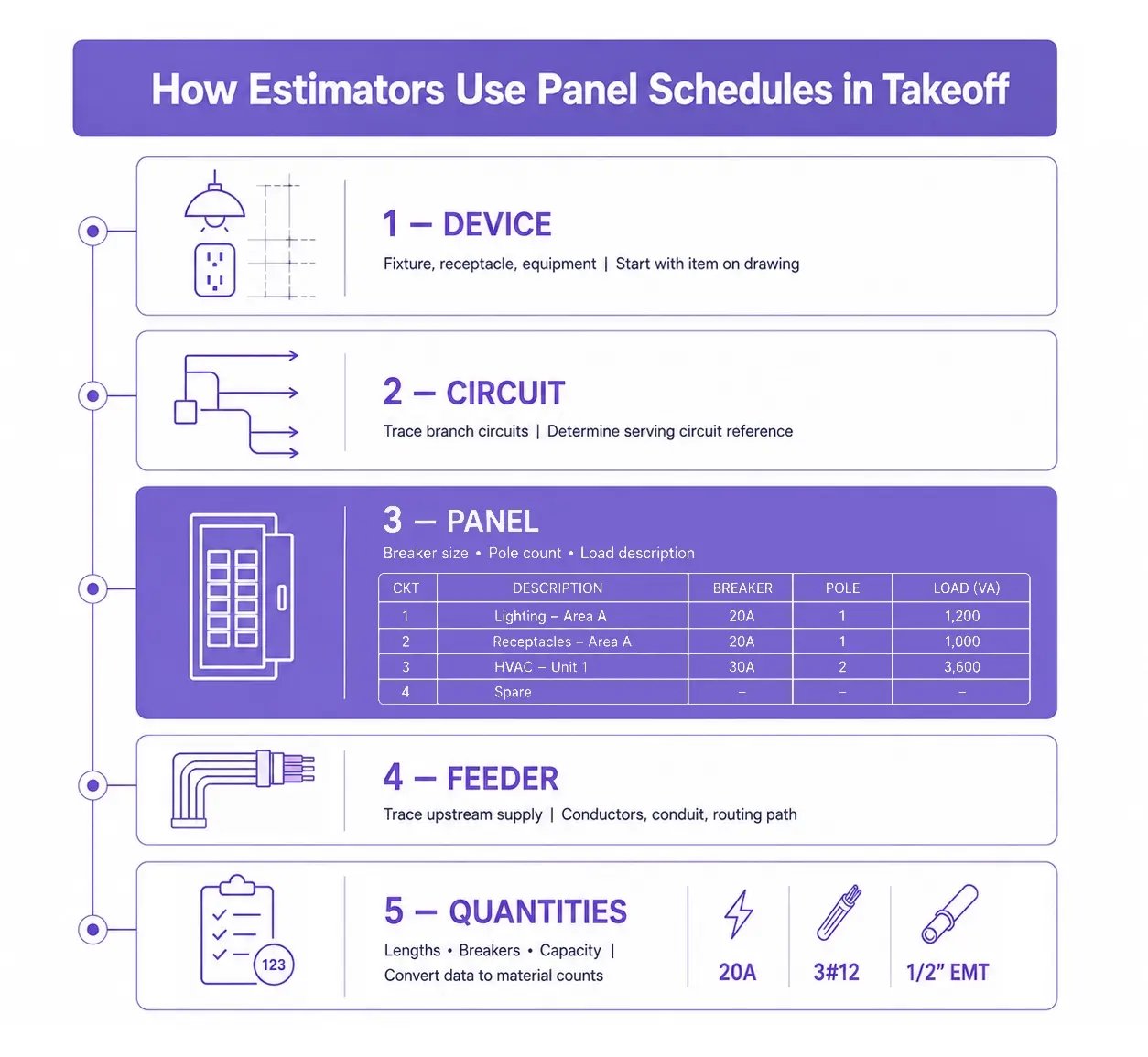
This is why the panel schedule, symbol legend, and floor plan need to be read together. The floor plan shows where devices are located, the symbol legend explains what those devices are, and the panel schedule shows how they are circuited and distributed. Without the schedule, the plan is only a map of symbols. With it, you can verify circuit intent, check whether the design is complete, and build a takeoff that reflects the real electrical scope. It can also support related checks, such as whether feeder lengths and connected loads warrant a closer look at voltage drop during estimating.
Beyond takeoff, panel schedules are also central to BIM workflows. In that context, the schedule is more than a printed table. It is tied to panel data, circuit assignments, and the properties of modeled electrical fixtures and equipment. When the model is accurate and well maintained, those connections help designers, estimators, and coordinators verify that circuits, panel names, load information, and connected devices stay consistent across drawings, schedules, and model elements.
Accurate, up-to-date panel schedules are especially valuable during coordination and clash review. When an MEP coordinator needs to understand what a conduit serves, where a circuit originates, or whether equipment connections are represented correctly, the panel schedule provides the quickest path to an answer. It helps the team verify routing assumptions, resolve mismatches between the model and the drawings, and avoid carrying outdated circuit information into procurement or installation. In that sense, a current panel schedule supports not only estimating, but also cleaner coordination across the full project team.
Even with that value, panel schedules still create a manual bottleneck for many estimating teams. On every revision, across every panel and project, someone has to read the schedule, transpose circuit information into spreadsheets, and reconcile it with the floor plan. That process is slow, repetitive, and vulnerable to missed rows, inconsistent naming, and rework that reduces bid efficiency. Automated panel schedule extraction removes that bottleneck by reading each circuit row directly from the PDF and tying it to the plan.
One alternative is to treat the panel schedule as structured project data rather than static text. An AI system can read the PDF, extract each circuit row, and connect that information to the corresponding symbols and devices shown on the plan. In practice, that means schedule data, circuit grouping, and branch routing can be interpreted together instead of being rebuilt by hand after every update. For estimating teams, the result is a faster workflow with fewer transcription steps and a more consistent basis for takeoff.
That is the approach used by Drawer AI, which combines schedule reading with circuit grouping and branch routing in one workflow. In a case study, Starr Electric Company reported 72% time savings for power devices and 81% for lighting fixtures on a large cancer center project while processing more than 3,200 fixture symbols and more than 3,300 receptacle symbols. Drawer AI's single-line diagram and plan equipment detection is also rolling out in 2026, adding panel and equipment extraction directly from SLD pages. Used carefully, tools like this do not replace estimator judgment; they reduce repetitive data handling so teams can spend more time reviewing scope, assumptions, and risk. Building a short list of accuracy checks for automated takeoff into that review keeps the extracted data reliable.
Reading a panel schedule well means more than recognizing columns and circuit numbers. It means understanding how devices, circuits, panels, and feeders connect so you can price work accurately, catch scope gaps early, and move through takeoff with more confidence. Whether you are reviewing a standard panelboard schedule, tracing 3-phase loads, or coordinating model data, the schedule is one of the most useful tools in the electrical set.
To see what automated schedule reading looks like in practice, book a Drawer AI demo. It links circuit-grouping and branch-routing output back to the panel schedule and the floor plan, so the takeoff stays consistent across every revision.

14425 Falcon Head Blvd
Building E, Suite 100,
Austin, TX 78738
Created by Estimators, Powered by AI and Innovation
Copyright © 2026 Drawer AI. All rights reserved.