AI



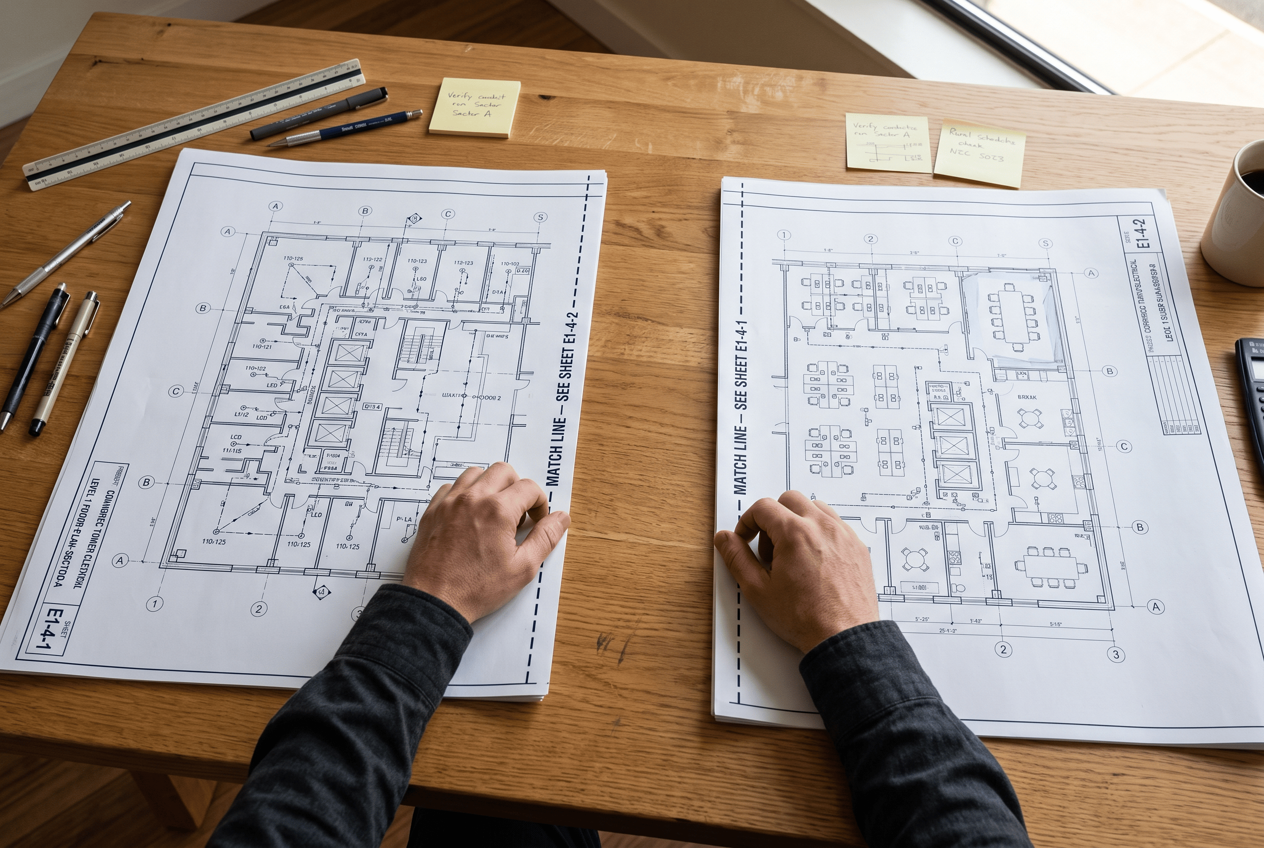

Opening a 48-sheet commercial electrical package for a large-scale project like a mixed-use commercial complex can be overwhelming. Your task is to orient yourself, locate the main distribution equipment, and trace circuit pathways. However, a single floor layout for these massive commercial buildings cannot physically fit onto a standard architectural sheet at a readable scale. To maintain legibility, designers split layouts across multiple pages, inserting a heavy dashed boundary known as a match line.
Table of Contents
Mastering how to read a match line and navigate a key plan is critical for executing fast, accurate commercial takeoffs. In this guide, we break down these multi-sheet navigation tools, using real-world scenarios from commercial plans, footprints, and wiring layouts as case studies. We will show you how to trace circuit runs and count devices across sheets without missing a single line item. "Match line" and "matchline" are used interchangeably in commercial estimating, so you will see both spellings throughout this guide.
Large electrical PDF sets are hard to manage because a single commercial project spans dozens of sheets tied together by match lines and a key plan. Estimators must mentally stitch the set, track devices and circuits that cross sheet boundaries, and re-check everything when a revision changes one sheet. The difficulty scales with sheet count.
A match line on construction drawings is a heavy, prominent dashed or chained line that marks the exact boundary where a building's layout is cut and continued onto an adjacent drawing sheet. It indicates to estimators and field installers that everything on one side of the boundary is detailed on the active sheet, while the rest of the layout is continued on a separate page.
Match lines exist because commercial building footprints are too large to display on standard ARCH D (24" x 36") or ARCH E1 (30" x 42") sheets at a readable scale. To preserve the legibility of circuit numbers, symbols, and notes, designers maintain standard scales like 1/8" = 1'-0" or 1/4" = 1'-0". At 1/8" scale, an ARCH D sheet can only cover an area of about 192' by 288'.
When a project exceeds these limits, designers split the footprint into sectors (e.g., East and West wings). A match line in construction drawings connects these sections. Every matchline is accompanied by a bold reference label directing the estimator to the adjoining page. For example, as shown in Figure 1, a vertical boundary line on first-floor plan sheet E1-4-1 might read: “MATCH LINE - SEE SHEET E1-4-2”. On the corresponding sheet E1-4-2, you will find a matching vertical boundary line labeled “MATCH LINE - SEE SHEET E1-4-1”, linking the sheets together.
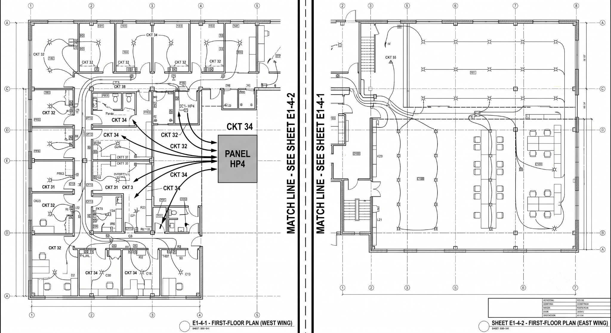
Figure 1. Match line connecting sheets E1-4-1 (West Wing) and E1-4-2 (East Wing).
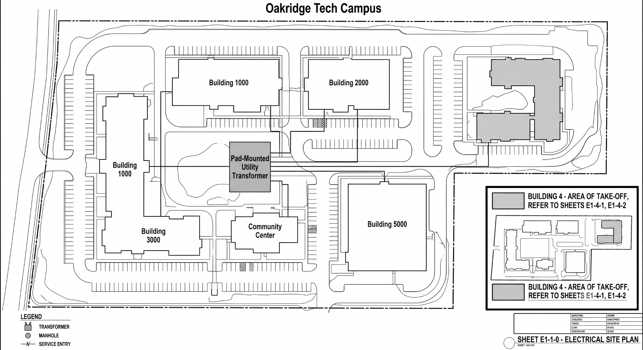
To understand why sheets are split, look at the footprints of commercial structures. Squeezing a 150,000 sq ft, three-story facility like Building Type 4 at a tech campus onto a single sheet results in an unreadable cluster of conduits, symbols, and labels.
To maintain design clarity, the MEP design team splits the Building Type 4 electrical plans across Sheet E1-4-1 and Sheet E1-4-2. This division allows the designer to display detailed branch circuits, panelboards, and equipment at a readable scale.
While estimators historically laid paper blueprints side-by-side to align these boundaries, modern estimators must navigate these divisions digitally as separate pages in a PDF viewer, creating a significant coordination bottleneck.
While match lines mark the sheet boundaries, the key plan provides the overall master layout. A key plan (interchangeably called a floorplan key or floor plan key) is a small, simplified building footprint diagram positioned in the corner of a detailed floor plan sheet.
This miniature map displays the overall building footprint, shading or highlighting the specific sector detailed on the active sheet. For commercial estimators, the key plan is vital for three main reasons:
For example, on the Electrical Site Plan (Sheet E1-1-0) for the commercial tech campus, the entire property footprint is mapped, showing the relative locations of all building structures. Localized floorplan keys are embedded on the detailed floor plans to show exactly how the electrical systems of each wing are divided for takeoff.
Navigating a matchline on drawings during a commercial bid requires a disciplined approach to prevent counting or circuit-tracking errors. Here is the standard methodology for tracing runs across sheet divisions:
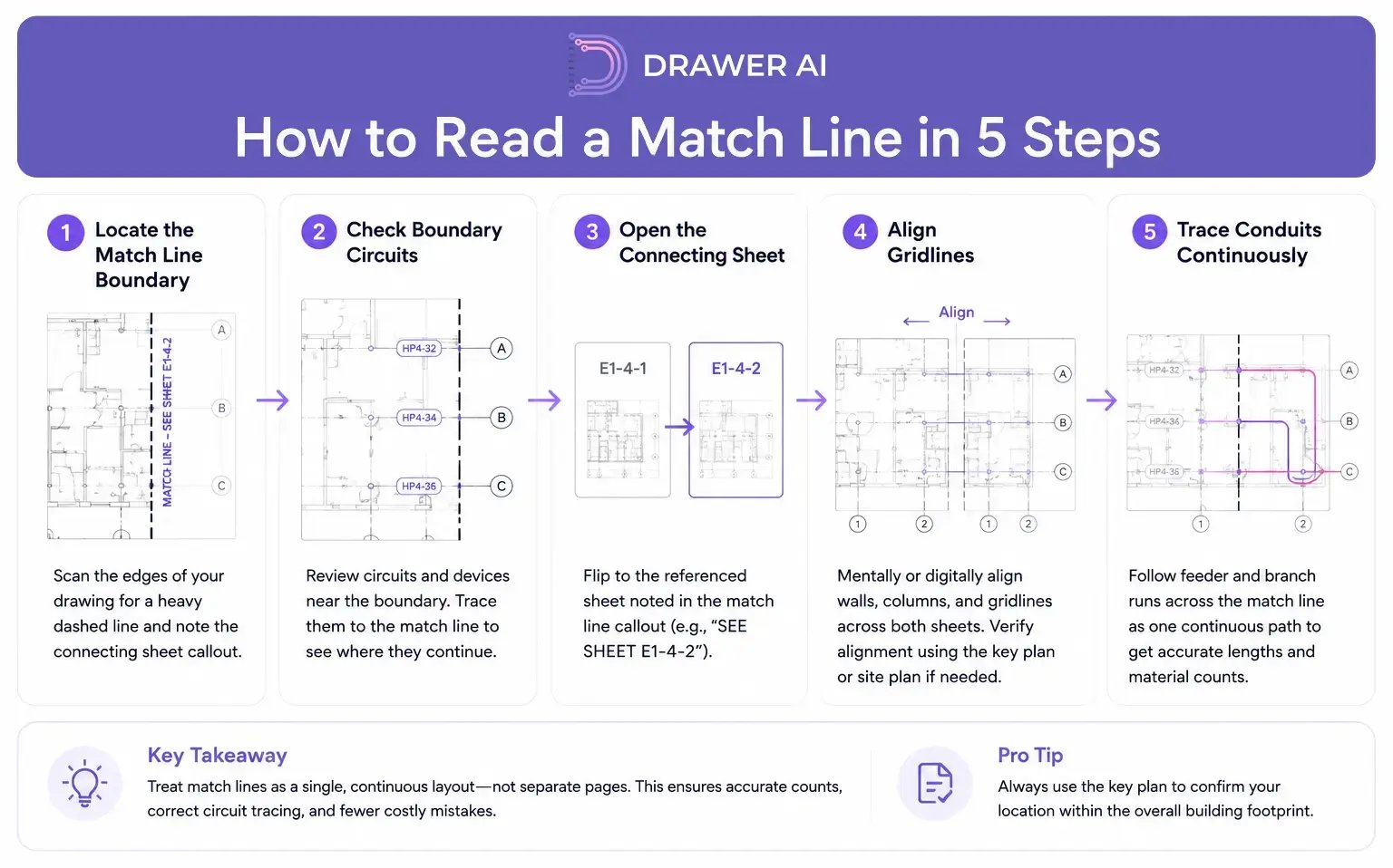
Scan the edges of your detailed floor plan for a heavy dashed line. Identify its connecting sheet callout (e.g., "MATCH LINE - SEE SHEET E1-4-2" on the first-floor plan E1-4-1).
Before changing pages, analyze circuit pathways and device counts near the border. For example, trace the corridor lighting or exterior mechanical room heaters on Panel HP4 (circuit 32 or 34) to see where they intersect the boundary.
Flip to the referenced page (Sheet E1-4-2) and locate the corresponding boundary line along its edge.
Mentally or digitally align the physical walls, columns, and structural trusses on both sides of the match line. If architectural features do not line up perfectly, check the master floor plan key or architectural site plan to verify alignment.
Follow the circuit or feeder runs continuously across the boundary line. Treating the split as a single physical conduit run rather than two separate paths ensures an accurate material length calculation.
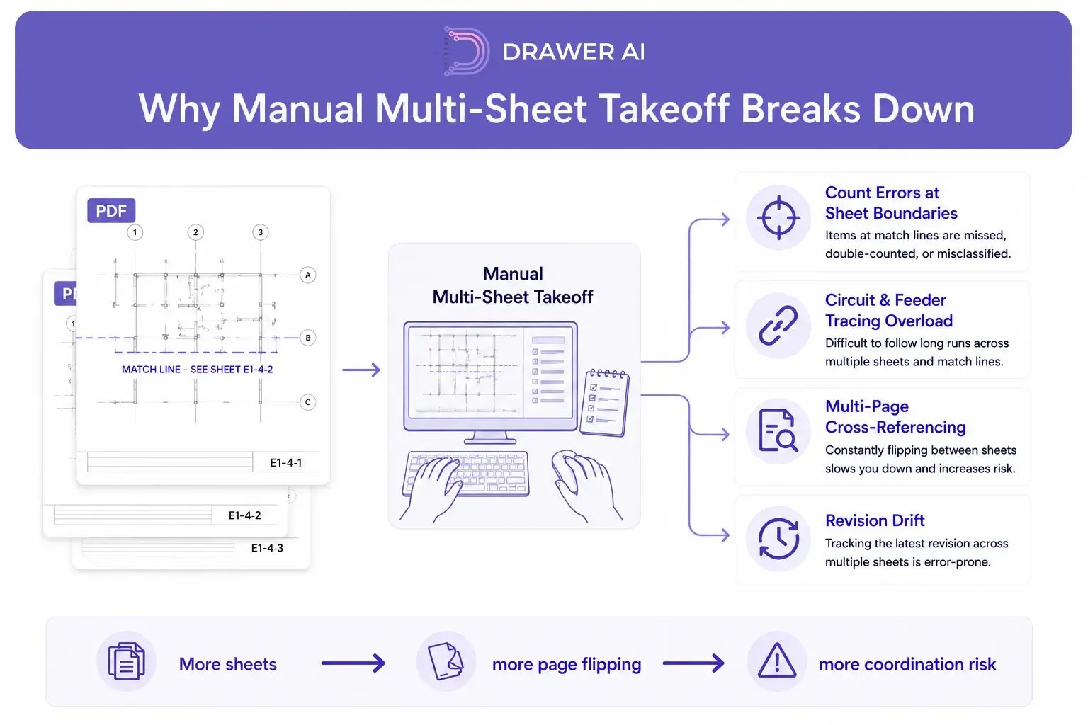
On any large commercial bid, manual takeoff is structurally slow and highly prone to costly errors. When estimators must manually track match lines and key plans across dozens of PDF pages, several major plan coordination pain points emerge:
To solve these multi-sheet bottlenecks, forward-thinking contractors are adopting automated takeoff solutions. Drawer AI addresses this pain point directly with automated stitching, a standard feature across its Starter and Enterprise tiers on its pricing page.
Instead of forcing estimators to mentally connect plans across different sheets, the software merges the separate PDF sheets into a unified floor layout by aligning their shared column grids, joining the entire multi-page drawing set into a single, continuous takeoff workspace.
This continuous workspace transforms multi-sheet takeoffs:
The commercial impact of this technology is illustrated by the Starr Electric case study. Faced with a large-scale project containing 3,284 lighting fixtures and 3,361 receptacles, the estimating team utilized Drawer AI to automate their takeoff. The team completed the takeoff with a 76.1% time savings compared to their manual process.
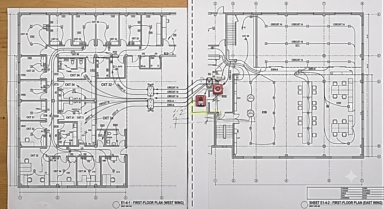
Figure 2. Unified floor layout of sheets E1-4-1 (West Wing) and E1-4-2 (East Wing) using automated stitching.
Match lines and key plans are the indispensable navigation coordinates of modern commercial electrical drawing sets. Reading them confidently is the difference between an accurate takeoff and a missed line item; reading them efficiently is the difference between a competitive bid and a slow one.
By automating the multi-sheet alignment process, Drawer AI removes the manual page-flipping bottleneck from your workflow. This automation allows your estimating team to focus entirely on building highly accurate, competitive bids that protect your margins and win more projects.
Ready to eliminate multi-sheet takeoff pain and accelerate your bidding process? Book a demo with Drawer AI today to see how our automated stitching feature can transform your commercial estimating workflow.
A commercial project is split across many sheets connected by match lines and a key plan, so estimators have to stitch the set together by hand, track devices and circuits that continue across sheet boundaries, and reconcile the panel schedule against device locations on separate sheets. Every revision risks misaligned sheets and inconsistent counts.
Large lighting projects pile hundreds of fixtures across many reflected-ceiling-plan sheets, each referenced by a type code to a schedule on a different sheet. Counting and cross-referencing all of that by hand across a multi-sheet PDF set is where scope gets missed. Automated stitching and fixture detection consolidate the set so counts are not tracked sheet by sheet.

14425 Falcon Head Blvd
Building E, Suite 100,
Austin, TX 78738
Created by Estimators, Powered by AI and Innovation
Copyright © 2026 Drawer AI. All rights reserved.