
AI




Conductor derating is one of those NEC tasks that looks simple until a raceway carries more circuits than expected or a run crosses a hot mechanical space. For commercial estimators, the practical question is usually immediate. What multiplier applies, and does it change the conductor size already carried in the bid?
Table of Сontents
Two different NEC rules drive most conductor derating decisions. Ambient temperature correction accounts for the temperature around the conductors and uses Table 310.15(B)(1)(1). Current-carrying-conductor adjustment accounts for the thermal effect of multiple loaded conductors sharing a raceway or cable and uses Table 310.15(C)(1). The factors are determined separately and, when both apply, they are used together.
The NEC generally uses the terms correction and adjustment rather than “derating.” This article uses derating as the umbrella term because that is how estimators commonly search for the calculation. The two NEC concepts remain distinct throughout.
For more than three current-carrying conductors, Table 310.15(C)(1) establishes the adjustment factor used against the applicable ampacity value. The chart is simple; getting the conductor count right is the critical step. For a live bid, that makes the conductor count the first thing to verify before pricing an upsize.
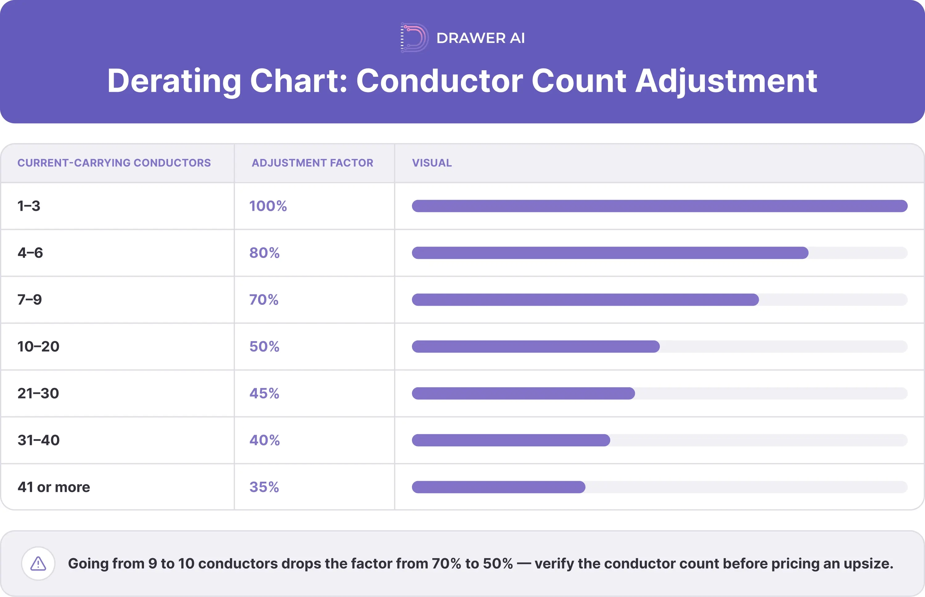
The cost jump can be abrupt. Going from nine current-carrying conductors to ten changes the adjustment factor from 70% to 50%. That is why conductor count is not a detail to leave until after the takeoff: one additional circuit can change wire size, raceway strategy, and labor.
This adjustment is separate from physical conduit fill. A raceway can pass the Chapter 9 fill calculation and still require conductor adjustment under 310.15(C)(1), or the reverse. Estimators need to check both.
Table 310.15(B)(1)(1) addresses a different condition: ambient temperature. The commonly used ampacity tables are based on a 30°C (86°F) reference ambient. A correction factor applies when the actual ambient differs from that basis.
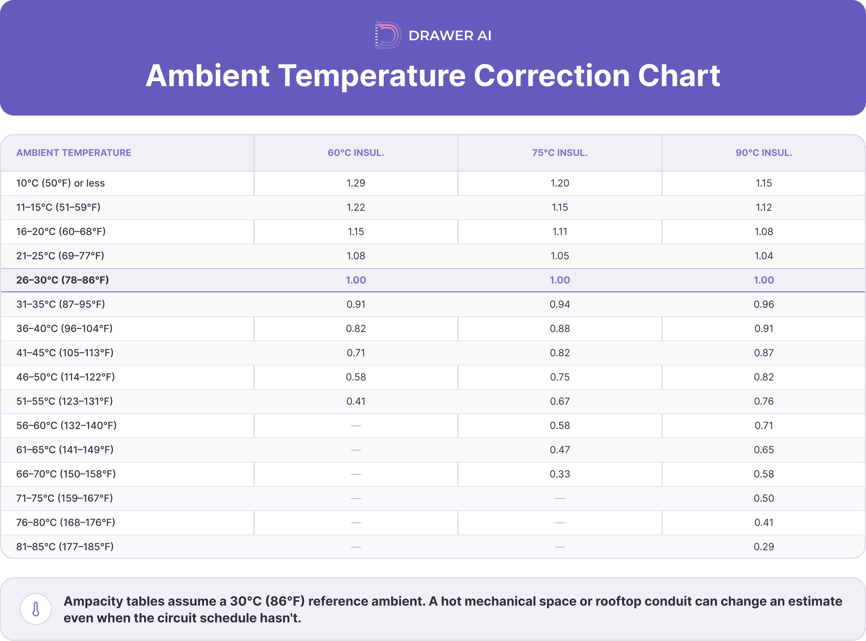
For a 90°C-rated conductor such as THHN, an ambient in the 36–40°C range uses a 0.91 correction factor. That factor is not the same thing as the 80%, 70%, or 50% adjustment caused by conductor count. If both conditions exist, both have to be accounted for.
A rooftop conduit on an office building, a hot mechanical penthouse, or a boiler room can therefore change an estimate even when the circuit schedule itself has not changed. The estimator needs the actual installation condition. The panel load alone is not enough.
The cleanest way to avoid mistakes is to keep the two questions separate. Temperature correction and conductor-count adjustment answer different questions. They should not be treated as interchangeable multipliers.
First ask: what ambient temperature correction applies to this conductor and insulation rating? That answer comes from 310.15(B)(1)(1). Then ask: how many current-carrying conductors share the raceway or cable? That answer drives the adjustment factor under 310.15(C)(1).
When both apply, the working relationship is:
Adjusted ampacity = base ampacity × temperature correction factor × conductor-count adjustment factor
The base ampacity comes from the applicable ampacity table, commonly Table 310.16 for the types of conductors seen on commercial branch work. The insulation temperature rating can be used in the derating calculation where permitted. The final allowable ampacity still has to respect equipment termination temperature limitations and the other applicable NEC sizing rules.
That last check matters. A calculation that produces a mathematically acceptable number is not automatically a complete conductor-sizing decision. Terminations, overcurrent protection, conductor material, insulation type, load characteristics, and project specifications still govern the final selection.
The multiplier is easy to look up. The count is where many estimates go wrong. Start with the current-carrying-conductor rules in 310.15(C)(1), then apply the neutral and grounding provisions in 310.15(E) and 310.15(F).
Ungrounded phase conductors carrying load are current-carrying conductors. Spare conductors are included in the count, and each current-carrying conductor in a paralleled set is counted individually. Conductors connected to components that cannot be energized simultaneously are not all counted as simultaneously current carrying. Equipment grounding and bonding conductors are not counted for the 310.15(C) adjustment.
Under the 2026 NEC structure in 310.15(E), a neutral in a two-wire line-to-neutral circuit is current carrying. A neutral in a three-wire circuit made up of two ungrounded conductors and the neutral from a four-wire, three-phase wye system is also treated as current carrying. On a four-wire, three-phase wye circuit where the major portion of the load is nonlinear, the neutral is current carrying because harmonic current can materially load it.
By contrast, a neutral that is not in one of those conditions and carries only the unbalanced current of the other conductors of the same circuit is not treated as current carrying for this adjustment. That distinction is especially important in offices, data-heavy tenant spaces, lighting systems with electronic drivers, UPS-backed loads, and industrial areas with power-electronic equipment. The circuit configuration determines the neutral treatment.
Consider a panel room where several branch circuits leave the same panel in a shared raceway. Counting only “hots” by habit can understate the current-carrying-conductor total if the neutrals in those circuits meet the NEC conditions for counting. The wrong count means the wrong row in the derating chart.
The reverse mistake also happens. Counting every equipment grounding conductor as current carrying can push the estimate into a lower adjustment band unnecessarily. The count should follow 310.15(C)(1), 310.15(E), and 310.15(F), not a blanket rule such as “count every wire in the pipe.” Before applying the table, also check the applicable 310.15(C)(1) exceptions, including qualifying raceway segments not exceeding 24 inches.
For a live bid, the conductor-derating check can be kept to five decisions.
1. Identify the conductor material, insulation type, temperature rating, and base ampacity from the applicable ampacity table.
2. Determine the expected ambient temperature along the run and select the correct 310.15(B)(1)(1) correction factor.
3. Count the current-carrying conductors under 310.15(C)(1), including spares and current-carrying conductors in paralleled sets; account for conductors that cannot be energized simultaneously; apply 310.15(E) and 310.15(F); check applicable exceptions; then select the adjustment factor.
4. Apply both factors when both conditions exist.
5. Verify the resulting conductor against termination limits, overcurrent protection, equipment requirements, project specifications, and any other applicable NEC provisions.
For a commercial estimator, step three deserves the most attention. The conductor count can change as routing develops. A takeoff that assumes separate home runs may produce a different wire size than a coordinated route that consolidates several circuits into one pathway.
That is also why derating is not just an engineering calculation. It is a routing calculation. It is also a pricing calculation.
Assume an industrial mechanical area has four three-phase, three-wire 20 A branch circuits routed together in one EMT run. With three phase conductors per circuit, the raceway contains 12 current-carrying conductors. Assume no additional spare conductors or applicable adjustment exception changes that count.
Twelve conductors fall in the 10–20 band, so the 310.15(C)(1) adjustment factor is 50%. Using 90°C-rated copper THHN as the derating basis, #12 copper has a 90°C table ampacity of 30 A. Before considering any temperature correction:
30 A × 0.50 = 15 A
That is below the 20 A circuit requirement. #10 copper at 40 A in the 90°C column gives:
40 A × 0.50 = 20 A
before any other applicable limitation is checked. The estimate that carried #12 because “it is a 20 A circuit” would therefore miss the effect of the shared raceway.
Now add a 40°C ambient in a mechanical penthouse. The 90°C temperature correction factor is 0.91, so #10 becomes:
40 A × 0.91 × 0.50 = 18.2 A
Under those assumptions, #10 is no longer enough on the derating calculation alone. #8 copper, with a 90°C table ampacity of 55 A, gives:
55 A × 0.91 × 0.50 ≈ 25.0 A
after both factors, before the remaining code checks.
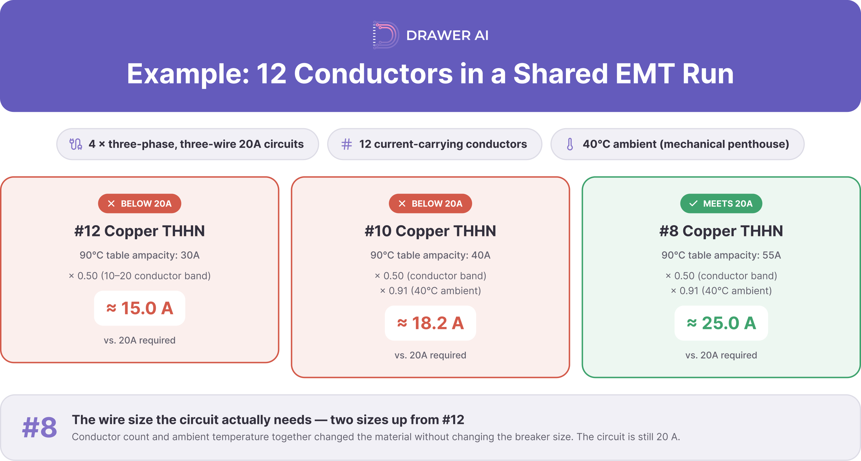
That is a large material change created without changing the breaker size. The circuit is still 20 A. The route and ambient conditions have changed the conductor economics.
Sometimes the less expensive answer is not a larger conductor. It is a different routing strategy. Splitting the run can change the conductor-count adjustment band.
Take the same four three-phase circuits. If the work can be split into two raceways with two circuits in each, each raceway has six current-carrying conductors. Six conductors use an 80% adjustment factor instead of 50%.
At the 30°C reference ambient, #12 THHN at 30 A × 0.80 gives 24 A before the final code checks. That can preserve the smaller conductor for a 20 A circuit where the rest of the installation permits it. The trade is additional EMT, fittings, supports, routing time, and labor.
This is the estimating decision that a derating chart alone cannot make. One option spends money on copper; the other spends money on raceway and labor. A short panel-room run may favor splitting raceways, while a long, congested industrial route may favor a conductor upsize. The bid should reflect the lower-cost constructible solution.
Wire derating affects more than the line item for copper. Upsizing conductors can trigger a larger raceway, different fittings, different pulling assumptions, larger junction boxes, and more labor. In dense panel rooms, it can also affect how many circuits can realistically share a pathway.
Temperature correction creates estimating risk when drawings do not state ambient conditions clearly. A rooftop office-building route or boiler-room run may look like a conditioned interior route on the electrical plan, yet require different conductor sizing. Routing context therefore affects quantity accuracy.
Cable derating and conductor derating also become revision-sensitive. Add one circuit to an existing shared run and the conductor count may cross from one adjustment band to another. Move a route from conditioned space into a hot mechanical zone and the temperature correction can change even though the panel schedule does not.
For senior estimators, that is why derating belongs in takeoff rather than final engineering cleanup. If the field discovers the issue later, the bid may already carry the wrong wire, conduit, or labor assumption. Correcting it then is usually more expensive.
The best time to catch conductor derating is while the route is still flexible. Once the conduit is installed, the available fixes become more expensive. Early review preserves more routing options.
If a panel-room design proposes twelve home runs sharing a 1-inch EMT, the estimator should not simply count twelve runs and pick a multiplier. The actual current-carrying conductors must be identified first. The raceway still has to be checked separately for physical conduit fill.
A rooftop office-building route should trigger the ambient-temperature check before the conductor is priced. A mechanical penthouse with both elevated temperature and heavily consolidated circuits should trigger both correction and adjustment. The final route determines which conditions apply.
The common thread is that derating follows the actual installation, not the symbol count on the floor plan. Good estimating connects circuit data, conductor count, environment, route, and wire size before quantities are locked. Applicable exceptions must also be checked before the adjustment factor is finalized.
That is the practical difference between using a derating chart as a lookup page and using it as an estimating tool. The chart gives the multiplier. The estimate has to decide what to do with it. At drawing-set scale, that is where Drawer AI comes in: we apply derating during automated branch routing and wire sizing.
Manual wire derating is manageable for one raceway. The problem grows when dozens of panels, hundreds of home runs, routing decisions, and shared pathways must stay synchronized across a commercial drawing set. A routing change can force the same check to be repeated.
Our workflow connects derating to circuit grouping, home-run placement, branch routing, automated wire sizing, and voltage-drop calculations. Software does not change the NEC rule. It keeps the same derating check tied to the route as the drawing set develops.
The distinction matters: the useful claim is not that software simply “handles derating.” The calculation is connected to routing. As circuits are grouped and branch paths are generated, conductor sizing can incorporate derating instead of asking the estimator to revisit every shared run manually after routing is complete.
That changes the scale of the task, not the underlying rule. The estimator still needs correct source information, the applicable NEC edition, project specifications, installation conditions, and review of exceptions or unusual loads. Automation does not turn an unknown ambient temperature or an incorrectly interpreted neutral into reliable input.
For commercial estimating teams, the value is consistency. The same correction-and-adjustment logic can be applied across many routed branches. The estimator can concentrate on conditions that actually require judgment: unusual environments, nonlinear loads, crowded pathways, alternate routing, and cases where splitting a run is cheaper than upsizing the conductor.
Seeing how this works on an actual drawing set is more useful than reading about it in the abstract – teams evaluating the approach can request a demo directly from Drawer AI to walk through branch routing on their own project files.

14425 Falcon Head Blvd
Building E, Suite 100,
Austin, TX 78738
Created by Estimators, Powered by AI and Innovation
Copyright © 2026 Drawer AI. All rights reserved.