
AI





Shop drawings vs design drawings can sound like two names for the same set until an electrical team has to turn design intent into something the field can actually install. Design drawings tell you WHAT the electrical system needs: symbols, panels, circuit intent, risers, schedules, and load information. Shop drawings tell you HOW that system will be built: real conduit routes, home runs, feeders, hangers and trapezes, dimensions, and coordinated installation geometry.
Table of Сontents
That distinction matters on commercial and industrial projects because the design set establishes electrical intent, while the project team still has to reconcile building conditions, other trades, panels, and available routing before installation. The practical shop drawings meaning is not “a more detailed design set.” It is coordinated, installable information developed from the design intent. Understanding shop drawings in construction means understanding how that design intent becomes field-ready electrical work. That interpretation — grouping circuits and turning design intent into routed electrical work — is where Drawer AI Takeoff and BIM Wizard automate different stages of the workflow, as explained below.
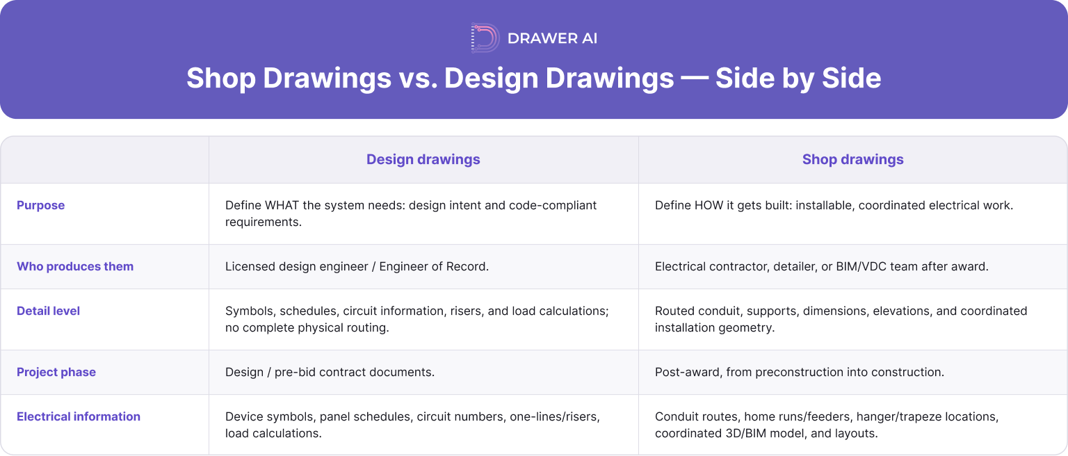
Electrical design drawings are the contract-document representation of the Engineer of Record’s intent. They establish what must be served and how the system is organized electrically, but they generally do not define every physical conduit path that will be installed.
A commercial electrical design set can include device symbols, panel schedules, circuit numbers, one-line diagrams, riser diagrams, feeder schedules, and load calculations. A commercial riser typically shows how electrical service and distribution equipment are interconnected, while panel schedules identify circuit assignments, connected loads, and equipment information. Conduit and feeder schedules provide conductor sizes, conduit requirements, and routing-related design information needed for coordination.
That information is enough to understand service relationships and design capacity. It is not the same as knowing the final path of each raceway through a coordinated building. The design drawing can establish what connects to what while leaving routing, elevations, support locations, and field coordination to the contractor and BIM/VDC team.
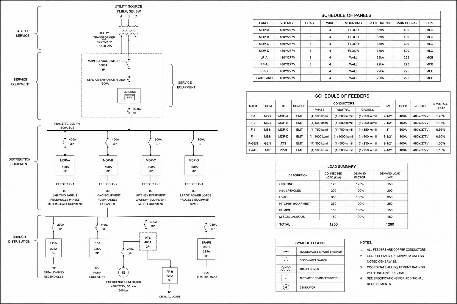
Figure 1. Commercial electrical riser excerpt showing service distribution, panels, and feeder relationships used to interpret design intent.
A practical shop drawings definition for electrical contractors is the coordinated installation information developed from the design set after award. Electrical shop drawings translate symbols and circuit intent into the actual model or layouts needed to build the work.
They can show real conduit runs, home runs, feeders, hanger and trapeze locations, dimensions, elevations, sleeves, and coordinated paths around mechanical, plumbing, structural, and architectural constraints. They are typically produced by the electrical contractor, detailer, or BIM/VDC team and then submitted through the project’s review and approval process.
A shop drawing is not simply a design drawing with extra notes. It resolves physical decisions the contract drawings do not carry. In a BIM workflow, the result may be a coordinated 3D electrical model in which conduits have defined sizes and spatial positions; model views and layouts then become the electrical shop-drawing deliverable used for coordination and field execution.
Electrical has one of the widest interpretation gaps between design intent and installable geometry. Other trades often begin with physical geometry already drawn: a duct or pipe has a visible path and size. Electrical design drawings often give the contractor symbols, panel assignments, circuit numbers, and riser relationships, while much of the raceway geometry still has to be created.
The electrical team must interpret that intent, group circuits, place home runs, and route each run while respecting constructability and code constraints. Raceway fill, conductor ampacity and adjustment, branch-circuit sizing, feeder sizing, voltage drop, and physical coordination all affect the routed result. Relevant NEC touchpoints include Articles 210 and 215 for branch circuits and feeders, Article 300 for general wiring methods, Article 310 for conductors and ampacity-related requirements, and the Chapter 9 tables used for raceway-fill calculations. These requirements must be applied to the actual project conditions.
Design drawings establish the required electrical system, but they do not define every field-installation decision. Shop drawings close that gap by translating the design intent into coordinated conduit routes, home runs, feeder paths, support locations, dimensions, and installation details that can be used in the field .
1. Design drawings — intent. The team identifies services, transformers, meter centers, panels, device symbols, circuit numbers, risers, feeder schedules, and design loads.
2. Estimating and takeoff. The team quantifies and organizes that intent. Devices and fixtures are counted, circuits are grouped, branch-routing quantities are developed, and the estimator creates clean input for the company’s estimating system.
3. BIM and shop drawings. The information becomes coordinated installation geometry. Conduit, feeders, home runs, and supports are routed around real building conditions, producing the model and layouts used as electrical shop drawings. In this design-to-BIM chain, shop drawings in construction are the coordinated output used to translate design intent into field-installable electrical work.

The handoff from estimating to BIM depends on getting the electrical intent right at the takeoff stage. Circuit grouping determines how many home runs the coordinated model will need, while feeder and panel information establishes the basis for downstream routing and equipment connections. A panel schedule misread during estimating can carry directly into BIM as a wrongly sized feeder, so accurate takeoff decisions are essential before installation geometry is developed.
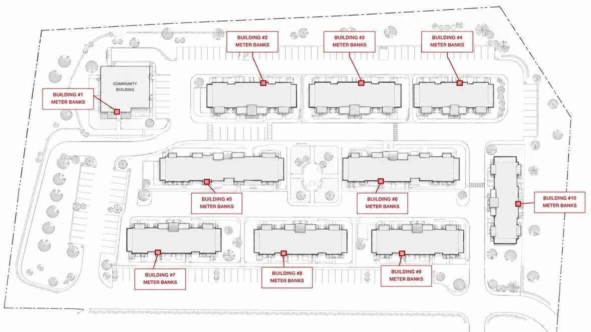
Figure 2. Illustrative site-level meter-bank reconciliation based on a real electrical service-mapping workflow.
A second multi-building electrical project showed the same principle from the load side. The electrical documents identified 1,096.30 kVA of connected load distributed across meter centers and house panels. A documented planning method then produced an estimated 220,445.40 kWh/year and a preliminary 183.70 kWdc solar target. The kVA came from the electrical load information; the kWh and PV size were derived planning values.
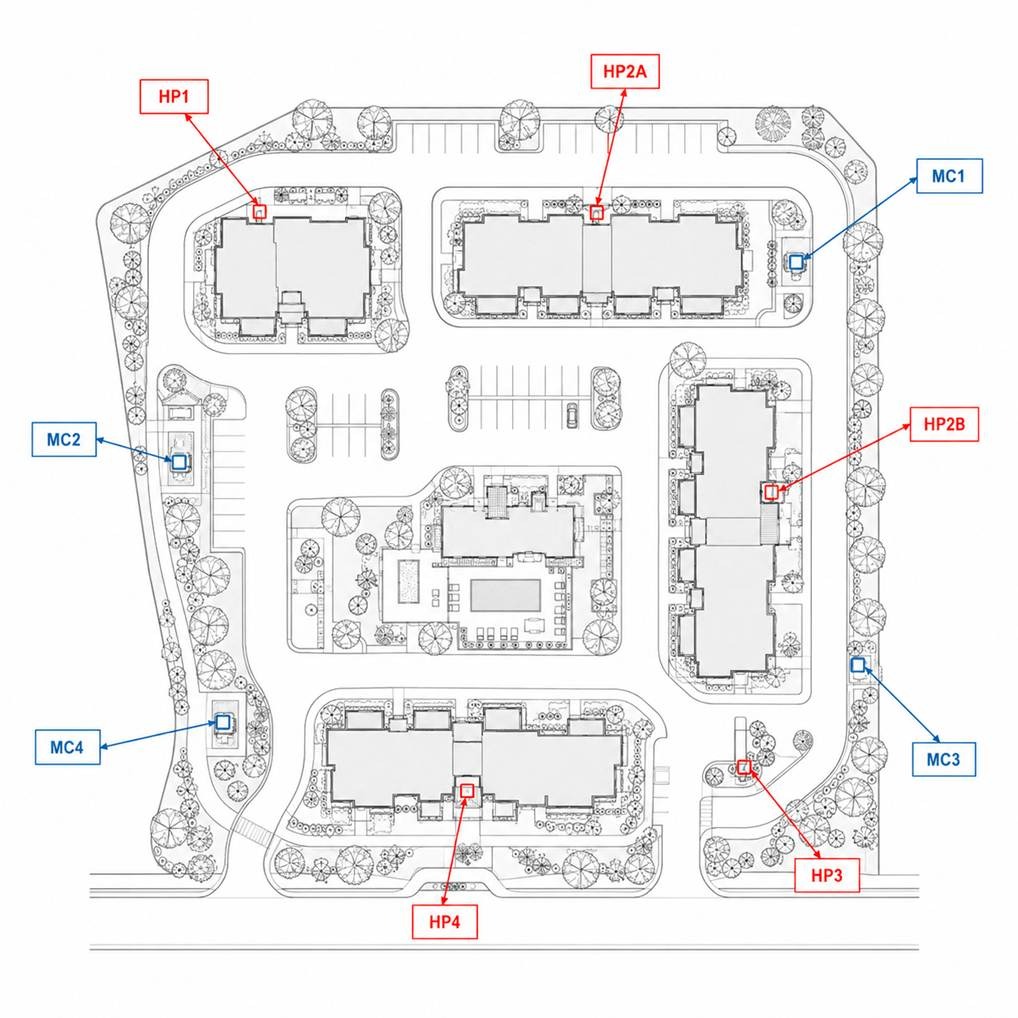
Figure 3. Illustrative meter-center and house/common-area panel layout based on a real electrical-to-solar coordination workflow.
Drawer AI Takeoff works at the estimating stage. It reads electrical PDF drawings, detects power devices and lighting fixtures, extracts and links panel/circuit information, groups devices by circuit, and generates branch routing.Drawer AI Takeoff also automates wire sizing, voltage-drop and derating calculations, and calculates total conduit and wire footage by circuit. The takeoff can be exported to Excel and to a marked-up PDF with device properties and routing. That output is upstream of labor and pricing: it provides organized quantities and routing information for the estimator’s own estimating workflow rather than applying the contractor’s labor units or producing a priced bid.
BIM Wizard addresses the next stage. It turns 2D electrical PDFs into a coordinated 3D Revit model with routed conduits. Its current scope includes feeders, home runs, branch conduits, intelligent sizing, and AI-powered clash detection. Deliverables include the 3D Revit model, PDF layouts, and an Excel conduit schedule. BIM Wizard does not replace Revit — it delivers a native Revit model that opens in the contractor’s existing BIM/VDC workflow.
The relationship is straightforward: design drawings → Drawer AI Takeoff / estimating → BIM Wizard / coordination → electrical shop drawings. Electrical BIM Explained provides additional context on the role of BIM in electrical construction.

The simplest way to remember shop drawings vs design drawings is design = WHAT; shop = HOW. The electrical design set establishes intent, symbols, panels, circuits, and loads; the shop-drawing process turns that information into routed conduit and an installable coordinated model.
A complete design set can still leave weeks of interpretation, routing, and coordination between project award and a shop-drawing package the field can build from. The design drawings establish the electrical intent, but the installation team must still translate that intent into coordinated pathways, equipment locations, supports, and constructible routing.
Drawer AI Takeoff helps structure estimating-stage information from design drawings, while BIM Wizard routes electrical scope into a coordinated Revit workflow. See Electrical BIM Explained for more on how BIM fits into electrical construction.

14425 Falcon Head Blvd
Building E, Suite 100,
Austin, TX 78738
Created by Estimators, Powered by AI and Innovation
Copyright © 2026 Drawer AI. All rights reserved.