AI



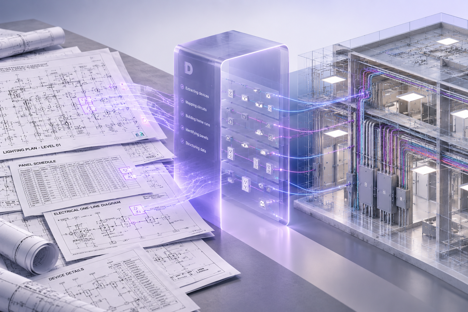

A finished electrical BIM model can look deceptively simple: equipment, panels, conduit, and circuit information organized inside a coordinated 3D environment. The work required to get there is not simple. For a commercial or industrial electrical contractor, the process usually starts with 2D construction documents and a stack of decisions that have to be made before the first meaningful conduit run is modeled.
Table of Сontents
The BIM/VDC team has to confirm the drawing set, identify devices and circuit information, build home-run logic, bring in architecture and the other trades, develop feeders, route raceways, resolve clashes, run QA/QC, and package the result for coordination and field use. The slowest part is often the front end: turning symbols, schedules, one-lines, notes, and plan references into structured electrical data that can actually be routed.
That front-end interpretation is also where AI is beginning to change the workflow. First, it helps to understand the sequence a contractor BIM/VDC team is actually managing.
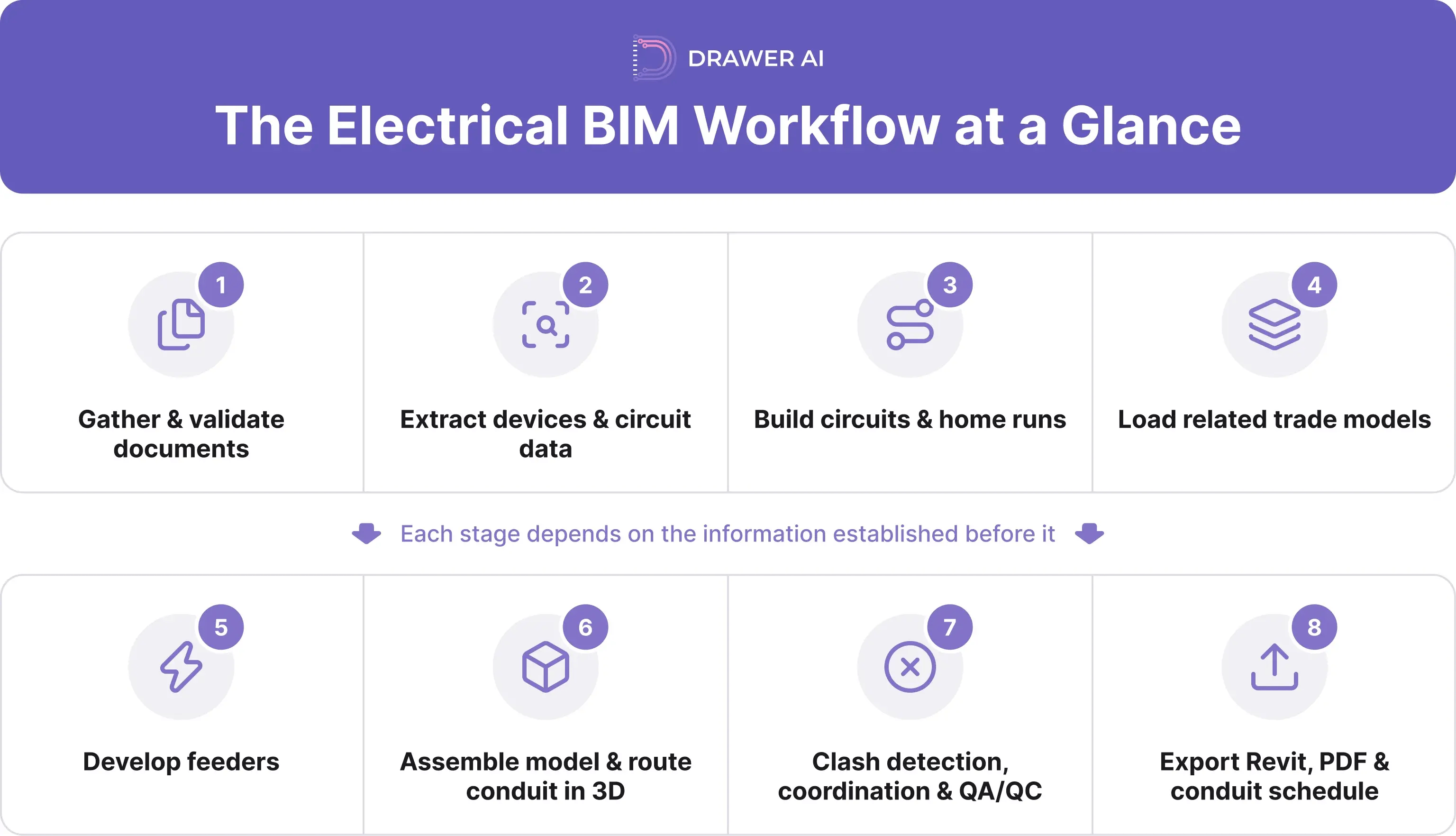
Figure 1. Typical electrical BIM modeling workflow for commercial and industrial projects.
Electrical BIM modeling is the process of turning design intent into a coordinated digital model that contains both geometry and electrical information. It is more than drawing conduit in 3D. A contractor model connects devices, panels, circuits, feeders, routing, elevations, equipment, and schedule data so the electrical scope can be coordinated and built. For the broader BIM context, see Electrical BIM Explained: What It Does & Why It Matters.
Revit supports electrical circuits and panel schedules, including circuit and load data tied to equipment, and it can schedule conduit runs for spreadsheet workflows. BIM/VDC teams use those capabilities to move from design documents toward a construction-oriented model for coordination, layout, prefabrication, and installation planning.
A model should not start with modeling. It should start with document control. The team needs the current electrical plans, panel schedules, one-lines or risers, details, specifications, addenda, and any approved design changes. It also needs the architectural, structural, mechanical, plumbing, fire-protection, and equipment models that define the space in which the electrical work has to fit.
The first questions are basic but critical: Which revision governs? Do the schedules agree with the plans? Is the architectural background current? What coordinate system and Revit version are required? What is actually in the contractor's BIM scope?
On a public-building electrical package, demolition plans, new-work lighting plans, fixture schedules, controls, and electrical details were distributed across separate sheets. No single page contained everything needed to understand the installation. The same reconciliation problem appears in BIM: the documents have to agree before they become reliable model data.
This is where the 2D set becomes model-ready data. Plan symbols must become devices with attributes. A receptacle may need a panel assignment, circuit number, voltage, mounting condition, and relationship to other devices on the branch circuit. Equipment may require the equipment schedule, a keyed note, and the one-line before its connection is clear.
The modeler is constantly cross-referencing: What is this device? Which panel and circuit serve it? Does the schedule agree with the plan? Is it new work, existing-to-remain, demolition, or an alternate? The work is repetitive but consequential; a wrong circuit relationship can produce clean-looking 3D geometry that is still electrically wrong.
Once the devices are identified, they have to be organized into circuits. The home run is the bridge between logical connectivity and physical routing: devices are grouped by circuit and tied back toward the serving panel so the team knows which connections must eventually become raceways and conductors.
This distinction matters. Revit can represent the electrical circuit and the connected loads, but logical connectivity does not automatically tell the contractor the best field route. The BIM team still has to determine where circuits can be grouped, where they should rise or drop, what corridors or racks make sense, and how to reach the electrical room without creating a coordination problem.
Electrical routing cannot be developed in isolation. Architectural and structural models establish walls, ceilings, shafts, beams, and penetrations; mechanical and plumbing models define many overhead constraints. Fire protection, process systems, equipment clearances, and specialty trades may add more.
A route that looks obvious on a 2D plan can run through a beam, cross a duct main, block access, or occupy an elevation another trade already needs. Linked models turn those hidden constraints into routing decisions before installation.
Feeders usually deserve attention before a large volume of branch conduit is committed. They connect major distribution equipment and often consume the most valuable routing space. Their size, bend requirements, access needs, and relationship to switchboards, panelboards, transformers, and other equipment can shape the rest of the electrical layout.
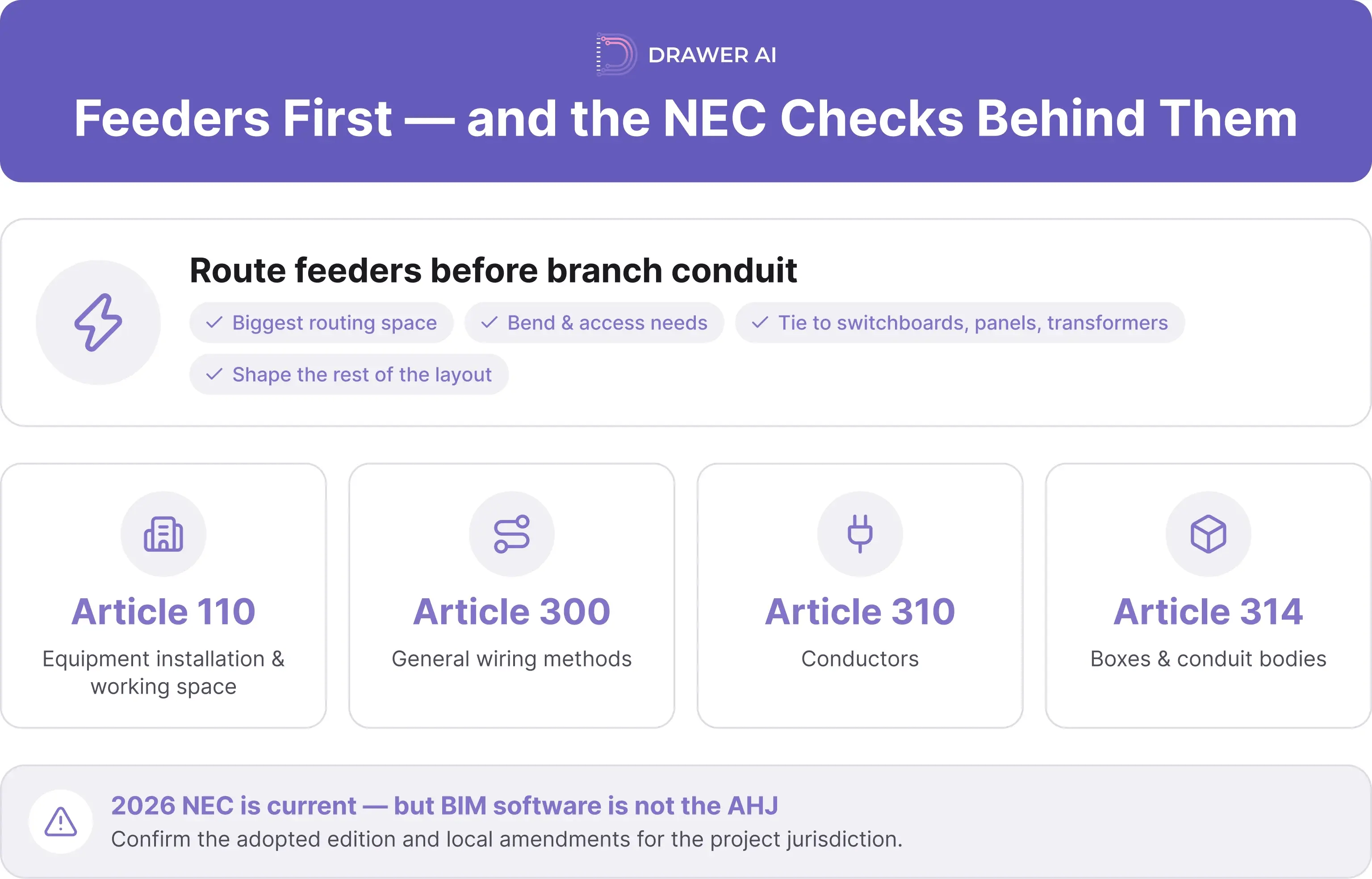
Code review is part of this work, but BIM software is not the authority having jurisdiction. Depending on the scope, the team may need to check requirements in NFPA 70 such as Article 110 for equipment installation and working space, Article 300 for general wiring methods, Article 310 for conductors, and Article 314 for boxes and conduit bodies. The 2026 NEC is the current national edition, but the adopted edition and local amendments still have to be confirmed for the project jurisdiction.
Now the model begins to look like what most people picture when they hear 'electrical BIM.' The team converts the electrical relationships into physical conduit paths. That means selecting elevations, planning racks, controlling bends, deciding where to cross walls, organizing vertical transitions, and keeping the raceway system constructible.
The shortest route is not automatically the best. A good path also considers access, support, prefabrication, sequencing, available space, and coordination priorities. In data centers, hospitals, manufacturing facilities, and high-rises, those decisions repeat hundreds or thousands of times.
Routing is rarely a one-pass exercise. After initial model population, the electrical scope is tested against other disciplines. Navisworks Manage's Clash Detective is commonly used to identify and track interferences. The value is not the clash list itself; it is deciding which conflicts are real, who should move, and what revised route remains constructible.
The cycle is familiar: route, clash, review, adjust, rerun. Hard clashes may require geometry changes, while clearance clashes may protect access or maintenance zones. False positives can also appear when search sets, tolerances, or rules are poorly configured.
A clash-free model is not automatically a correct electrical model. QA/QC has to check both geometry and information. Are all required devices represented? Do panel and circuit assignments agree with the source drawings? Are feeder origins and destinations correct? Are there duplicated or missing runs? Are elevations consistent? Have drawing revisions been incorporated? Does the conduit schedule agree with what is actually modeled?
The best review process also separates confirmed information from assumptions. If a value, route, or circuit relationship cannot be verified from the documents or coordination decisions, it should be flagged for resolution rather than quietly invented. That principle is just as important in BIM as it is in estimating.
The last step is turning the coordinated model into outputs the project can actually use. Depending on the contractor and contract requirements, that can include the native Revit model, coordination views, PDF layouts, spool or prefab information, and conduit schedules that can be exported for spreadsheet-based review and downstream planning.
The goal is continuity. The model, layouts, and schedules should come from the same coordinated information so a revision does not force the team to rebuild multiple disconnected records by hand.
From the outside, BIM time is often described as 'conduit modeling time.' That misses a major part of the workload. Before a modeler can route a conduit correctly, someone has to interpret the drawings, find the serving panel, understand the circuit grouping, confirm the relevant schedule information, and establish where the connection starts and ends.
That is why the biggest opportunity for automation is not just drawing faster. It is reducing the manual translation between a 2D electrical drawing set and structured, routable electrical data. Once that data exists, routing and coordination automation can attack the next bottleneck.
Different tools address different parts of the process. Augmenta focuses on raceway modeling, routing, and coordination, generating native Revit elements and applying routing constraints for iterative coordination on commercial project types such as data centers, manufacturing, high-rise, and healthcare.
Drawer AI approaches the workflow farther upstream. Its current BIM Wizard starts from the same 2D PDF electrical drawing sets contractors already receive. The current BIM Wizard converts those drawings into structured electrical data and generates native Revit models with feeders, home runs, and branch conduits. Its published deliverables include a 3D Revit model, PDF layouts, and an Excel conduit schedule.
That matters because the 2D-to-data step is where so much manual interpretation lives. Automating device detection, panel and circuit relationships, home-run structure, and initial routing can move the BIM/VDC professional away from repetitive model population and toward review, exceptions, coordination, constructability, and project-specific decisions.
A public Drawer AI case study with Starr Electric gives a useful scale reference. On a 300,000-square-foot cancer center construction-document set spanning eight floors, the workflow involved 3,284 lighting fixture symbols and 3,361 receptacle symbols. The case study reports 6,645 total symbols processed in about 5.5 hours versus roughly 23 hours for the traditional baseline, a 76.1% reduction for that takeoff-and-QA step. The same case study says branch-routing analysis surfaced discrepancies between panel schedules and floor plans before construction.
That result should not be read as 'AI did the entire BIM job 76% faster.' It is narrower and more useful than that: it shows how much time can sit in the repetitive detection, classification, and reconciliation work that feeds the model. The contractor still owns QA, project standards, coordination decisions, and final acceptance of the model.
These tools are not interchangeable. Revit is the modeling environment and data backbone for many electrical BIM teams. Navisworks supports model aggregation and clash coordination. Augmenta focuses on generative raceway routing. Drawer AI targets the earlier translation from electrical PDFs into model-ready data and routed Revit output.
For a contractor, the practical question is which manual step is consuming capacity. If the bottleneck is conduit routing, generative routing has clear value. If it begins with reading PDFs and building device/circuit relationships, upstream automation matters more. Many VDC environments will use several tools rather than one.
A reliable electrical BIM model is built in sequence. The documents have to be controlled. Devices and circuit information have to be interpreted correctly. Home runs and feeders have to be organized. The other trades have to be present. Raceway has to be routed in real space. Clashes have to be resolved. Then the electrical data and geometry both need QA/QC before the model becomes a field or coordination deliverable.
AI can compress several labor-intensive parts of that sequence, especially the translation from 2D drawings to structured electrical data and the repetitive work of conduit routing. It does not remove the need for an experienced electrical BIM/VDC team. It changes where that team's time is spent.
For larger contractors with in-house BIM departments, that can mean more project capacity without scaling manual modeling hours at the same rate. For smaller commercial and industrial contractors that currently outsource BIM, it can lower the amount of repetitive work required to build more of that capability internally. Either way, the important shift is the same: reducing the distance between the electrical drawings received at the start of the job and a coordinated model the project can actually build from.
Electrical BIM modeling is the process of converting electrical design information into a coordinated digital model that includes devices, circuits, panels, feeders, raceways, geometry, and associated data. For commercial and industrial electrical contractors, the workflow usually moves from document validation and data extraction through home runs, feeder development, 3D conduit routing, clash coordination, QA/QC, and final Revit/PDF/schedule deliverables.

14425 Falcon Head Blvd
Building E, Suite 100,
Austin, TX 78738
Created by Estimators, Powered by AI and Innovation
Copyright © 2026 Drawer AI. All rights reserved.